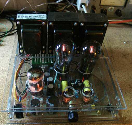
 A Tubelab SE in a clear Lexan case
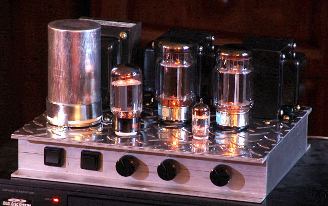 A new Tubelab SSE Amp
A Tubelab SE in a clear Lexan case
A new Tubelab SSE Amp
The TSE board shown in this web site is NO LONGER available. There are ZERO in stock, and none will be reordered.
It has been an old faithful for 14 years. Several hundred amps have been built, but all good things must come to an end……..only to be replaced by BETTER things. The filament regulator chip used in the TSE is no longer made….in fact Sharp is no longer alive, it is now part of the Foxconn empire.
The TSE is being redesigned to use a different regulator chip. In the process a list of requests from prior builders was collected and is being accommodated. The new board will be slightly bigger to handle 300B tubes, and provide more space around the heat sinks. More filtering has been added to the filament regulator circuit to handle 2A3’s without issue. I already have a prototype board running, but I expect that it will be 4 to 6 weeks before the design is fully tested and new boards are in stock. The progress of the new TSE-II can be followed on the Tubelab forum here:
https://www.diyaudio.com/forums/tubelab/331038-14-run-tse-die.html
There is already a new board in stock, but full web site ready build instructions are not ready yet:
https://www.diyaudio.com/forums/tubelab/316225-tubelab-universal-driver-board-2015-version.html
There are also one or two more new boards planned for 2019……stay tuned!
Our new address is:
Tubelab Inc.
73 Bottom Ln.
Moundsville, WV 26041
Welcome to the new Tubelab website, now powered by WordPress! After a long and tedious process, all of the content from the old site has been resurrected and reproduced here. The information has been reorganized into the categories that you see in the menu bar above. The Navigation Box on the right can also help to guide you.
We are still testing the new shopping cart experience. Until it is up and running, please use the usual method for ordering PC board via email using the instructions on the ordering page. New postal rates may apply.
I get far more email than I am currently able to answer. Considerable email asks “how do I order a board”? I have updated the PC board ordering page in an effort to reduce these emails. I get a few emails asking technical questions about the PC boards. These will all be answered, but lately the I can only respond to Tubelab email on weekends. Tubelab email access is forbidden at work, and lately I have been at work until late almost every weekday. For now I can still check in to the diyAudio vacuum tube forum at lunch and after 5PM from work. There is nearly always an active thread about Tubelab amplifiers under construction. The people are friendly and there are plenty of people who have already finished their Tubelab amps if I am not available. Anyone can read posts, but you need to register to post questions or download anything. I have started compiling a FAQ page based on previous email and forum posts. It will be added to this web site as time permits.
I am building this page on the road somewhere in western Pennsylvania. Sherri and I are staying at her mothers house for a short while. We should be returning to Florida in a week or so.
The communications industry has been hit hard by the economic downturn with hundreds of layoffs in the plant where I work. I am usually at work 10 to 12 hours a day lately doing my best to stay employed. Unfortunately no job is totally secure, and the expenses associated with Sherri's mom have forced a careful optimization of Tubelab's expenses. So for now, Tubelab is operating with a fraction of my time, none of Sherri's, and limited funds. The budget for new projects is very limited so except for small parts all development projects in 2009 will come from my "junk box" which fortunately is well stocked. There is no budget for transformers or other costly parts.
When the economy started to slow down last year, sales of PC boards dwindled too. This forced the delay in the launch of the Tubelab SPP. Fortunately it is nearly ready. For now future products must wait until the current new project (SPP) pays for itself.
There are two P-P designs currently under development. The “Small” one, now called the SPP, and the "Big" one, now called the Universal PP driver. The Small one has progressed to the "third prototype PC board" stage. It is currently going through my rigorous testing, and I have been using it for several experiments. I plan to take this design through to a production PC board, but it will not be ready until the 2nd quarter of 2009.
The circuitry is not all that unusual. I Have already been informed that it bears a resemblance to SY's "red light district" amplifier, and Morgan Jones "Bevois Valley" amp. The truth is that it is about as simple of a P-P amp that I could come up with that yielded good performance. All three of these amps look like descendants of the Williamson to me.
Why have I done "yet another version of this common design?" I have breadboarded countless variations of small P-P amps. Some used the 6AQ5 tube, and some used the 6BQ5 / EL84 tube. Every amp was evaluated for performance, simplicity, and most important, the ability to be assembled by builders of varying skill levels and work the first time. One of the main requirements was for a stable design that didn't require any component tweaking to make it work. This design worked out to be the best. I chose the 6BQ5 / EL84 tube mostly because that is what was requested in the email that I received. The 6AQ5 is cheaper but produces slightly less power, and a slightly different sound. I may produce a 6AQ5 version of this board if there are enough requests for it.
As usual the board can be wired for triode, UL and pentode mode. Provision for global negative feedback is available. It can be used if needed, and it is needed in pentode mode.
There have been the usual delays due to "trying to keep my day job" activities and Sherri being away for much of the year, but the most recent delays are for two good reasons. I got some $1 output tubes that may work in this amplifier, so I had to try them out. It turns out that a PC board change was required. During the development of the original board I built a hybrid amplifier that used a tube - mosfet "Darlington" connection for the output. Again a PC board change was needed. The changes have been implemented and a prototype board made. The board works as expected with 6BQ5's but I have not tested the other combinations yet.
I have included some photos below.
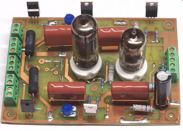
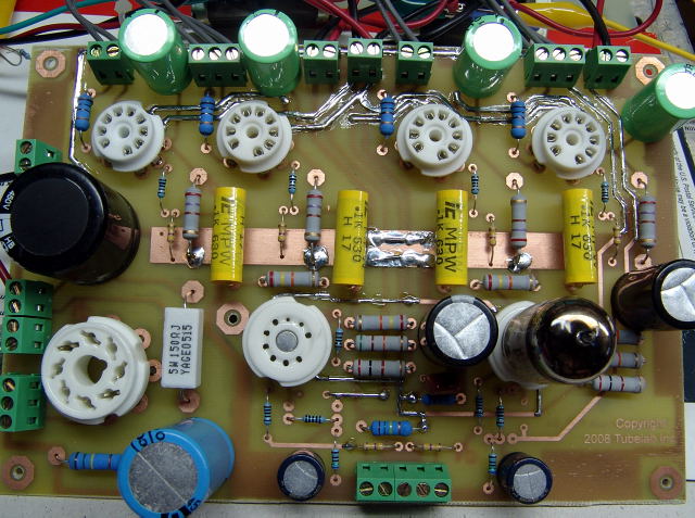 The first board, it hasn't seen any electricity yet.
A careful look will reveal my first problem with this board. The driver tube on the right is installed. The driver tube on the left, won't fit in the socket! The holes for pins 2 and 3 are smaller than the pins on the tube. Next time I'll look more carefully at the sockets before installing them.
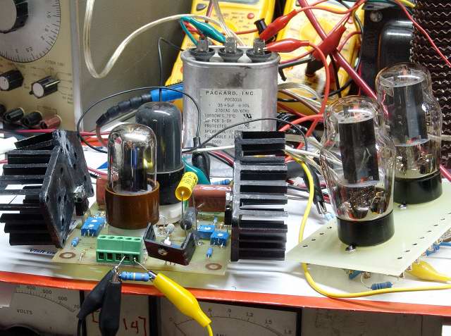
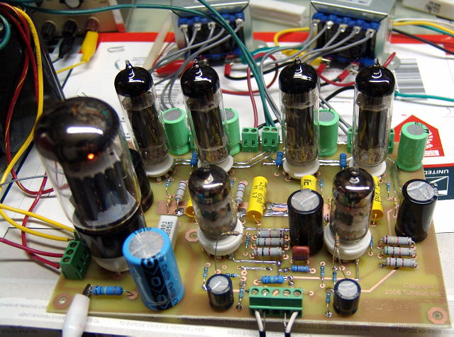 It is cranking some tunes here. The flying resistors are the GNFB resistors. I have not yet decided on an optimum value.
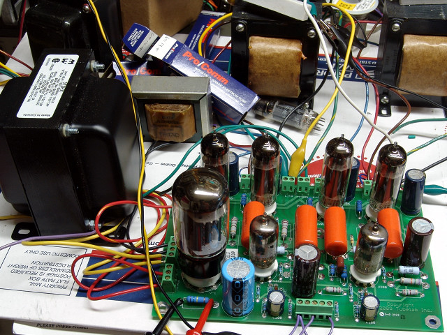
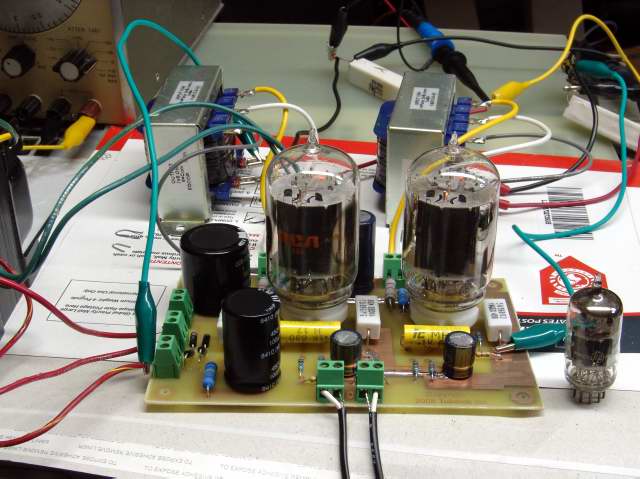
![]() I added some much bigger transformers for much bigger sound.
I added some much bigger transformers for much bigger sound.
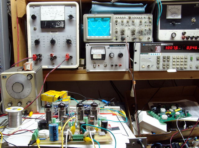 Board on test. Note the distortion number of 0.346%
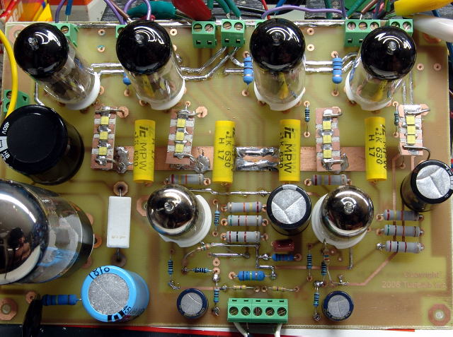
SY convinced me to try this. The cathode resistors and bypass capacitors have been removed and replaced with LED's. In this case three special LED's were mounted in series on a heat sink material.The amp does indeed sound fantastic with LED's in the cathodes of the output tubes. I am looking for an off the shelf LED that will work here. It may be included in the design.
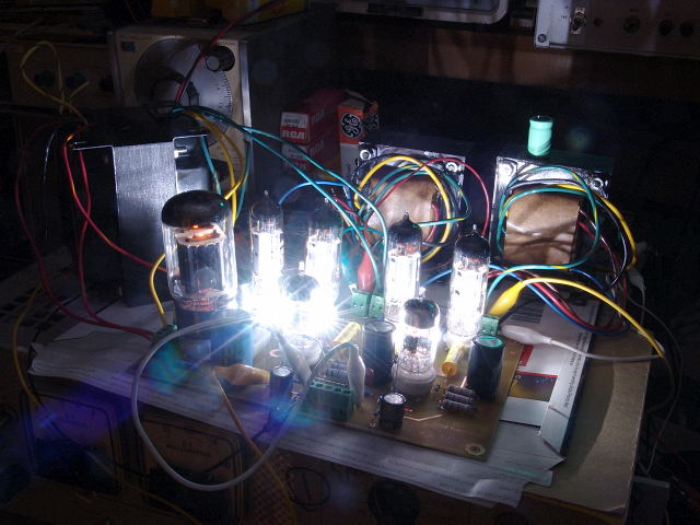 It can light up the whole room too!
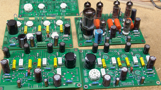
The SPP boards are in house. This one has been kicking out the tunes for a few weeks now.
It has also been the subject of some extensive experimentation. In fact I decided to build another one, and then three more were assembled so that I could shoot all of the pictures for the manual.
All of the pictures have been taken for the manual and I am currently putting it all together on my laptop while travelling. I have discovered a few photos than must be redone once I return home. We have ordered the parts for a small parts kit which will consist of everything needed to populate the PC board. Both should be ready within two weeks of my return to Florida.
The next step in the “not quite so Simple P-P” is a P-P Driver board. The design goals are simple, it needs to be capable of driving a pair of tubes to full power in P-P. It should be capable of driving anything from a pair of 6V6's or 6L6 type tubes in conventional grid drive up or cranking a pair of sweep tubes to near meltdown in screen drive or even cathode follower mode. This board must be able to drop in to the original 300Beast amplifier, replacing its driver board while offering equal or better sound quality.
OK, writing down some lofty goals on paper (or in the computer) is easy. Building the circuit and getting it to work is not. This project has been alive since before there was a Tubelab web site. In many ways it has evolved from my 300Beast amplifier. It incorporates a lot of the 300Beast design and many techniques that I have learned since the 300Beast was built.
I laid out this prototype PC board in a hospital waiting room in Pittsburgh during the Christmas (2008) holidays. I started building it when I got back to Florida. When I completed it and powered it up I found that I had swapped the top and bottom layers when making the board, resulting in a mirror image of what I laid out. After nearly tossing it in the trash, I realized that all I needed to do was solder a set of tube sockets on the back of the board. The board is alive and working now. More details are on the Universal Driver Board page.
I have received numerous requests for an amplifier using all octal tubes. Octal tubes use up more board space than miniature tubes and are usually more expensive, so I have not done a completely octal amplifier yet. I decided that a complete P-P amplifier would not fit on a single PC board if it used octal tubes, so an octal tube amp must be broken up into blocks. While working on the Universal Driver Board a thread developed on the diyAudio forum dealing with designing an amplifier using 6L6GC's in AB2. The thread originator desired to use 6SN7's for the driver tubes. I was assisting in a "paper design" effort by modifying a Universal Driver Board for this project. I got a little carried away and 350 forum posts later I had a working a prototype amplifier that used all octal tubes.
See the Octal Driver Board page for more details.
I have developed another future product, the Spud SE. This is a "really simple SE". It started out as an email conversation about "Spud Amps" and evolved into this. There was very little interest in this project until lately. In the past two months there have been a few questions about the availability of this board, unfortunately I don't have the time to work on it right now, and I am not sure that it would ever pay back the initial PC board design costs in today's economy. This one is on hold for now.
I got a lot of email about the MiniTron. Some called it cool, some thought it was criminal, most was positive though. Either way, the MiniTron and its derivatives will have to wait until I have more time. Circuit Cellar asked me to write an article about it for their magazine. That article is in the current issue of Circuit Cellar (Oct. 2009). I don't have the time right now to do any further development on the software. The MiniTron now sits, lonely, all alone in the closet, waiting for some attention.
The MiniTron amplifier was designed for entry into the Circuit Cellar / Microchip design contest. In a sea of microprocessor powered IC based gizmos this vacuum tube amplifier WON ONE OF THE CATEGORY PRIZES!!! It is featured in the Oct 2009 issue of Circuit Cellar magazine, and is currently on their web site.I will be posting much more information about this design in the coming months. You don't care anything about an amplifier that has more chips than tubes? I don't blame you, but this project has taught me a lot about the distortion producing mechanisms in vacuum tube circuits. I am using this information to design some radically new vacuum tube circuitry, that is silicon free, as well as some unique hybrid designs. Unfortunately the events outlined below have severely slowed down the progress. The amplifier you see above was completed in early October, and hasn't been touched since.
Progress has resumed slowly with the design of an all tube cathode follower amp incorporating some of the technology developed during the development of the MiniTron. A new page for this design will be created soon. One component of the MiniTron is the cathode follower amplifier, which still has its own page. The complete contest submission including schematics, source code, and design details can be found here:
http://www.circuitcellar.com/microchip2007/winners/MT2209.html