Table of Contents
- Getting Started
- Resistors
- Tube Sockets
- Semiconductors
- Capacitors
Final Assembly
- Checkout
- Setting the Bias
- Enclosures
Final Assembly
There are a few remaining items left to be installed on the board. They are all require some thought before installation. By now you should have determined the final application for this board. Read each section below carefully, and perform the steps that apply to your application.
Board Jumpers
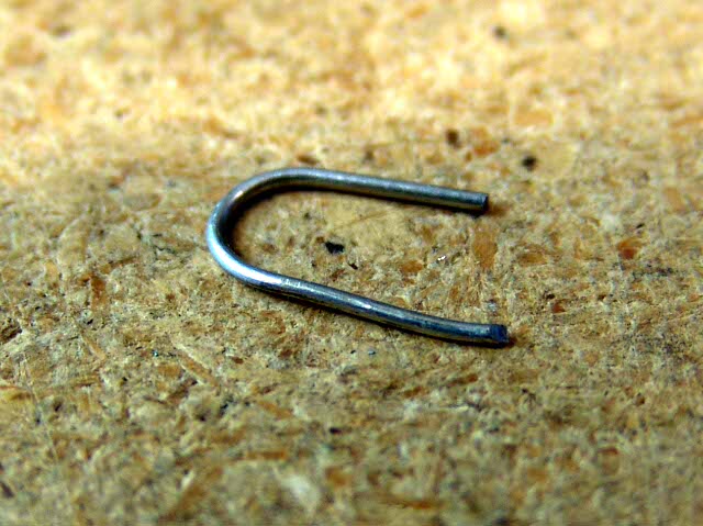
There are three locations on the board where a wire jumper must be installed. A piece of one of the resistor leads that was clipped off earlier can be used to make these jumpers. It it bent into a "U" shape and inserted into the board like a resistor. Then it is soldered and clipped like a resistor.
B+ Jumper
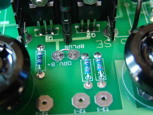 Here the B+ jumper is inserted in the holes.
There are two solder pads in the area between the output tube sockets, located between R34 and R18. They are marked BPLUS and DRV_B+. For use as a driver board in conjunction with an external power supply and PowerDrive board, these pads are left alone. The external power supply will be connected to these (and other) pads. For ALL other applications, including driver board use with an interstage transformer, place a jumper between these two pads.
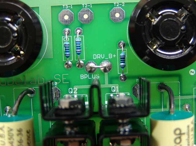 Bend the wire slightly, so that it won't fall out. Flip the board over and solder it in.
Filament Jumpers
There are two sets of jumpers that set the filament voltage that is provided to the output tubes. It is important to get both of them set right. The health of your output tubes depend on it. There are settings for 2.5 volts or 5 volts. For odd voltages, follow the 2.5 volt settings, and change the value of R1 to achieve the desired voltage.
5 volts (300B, NX-483 and others)
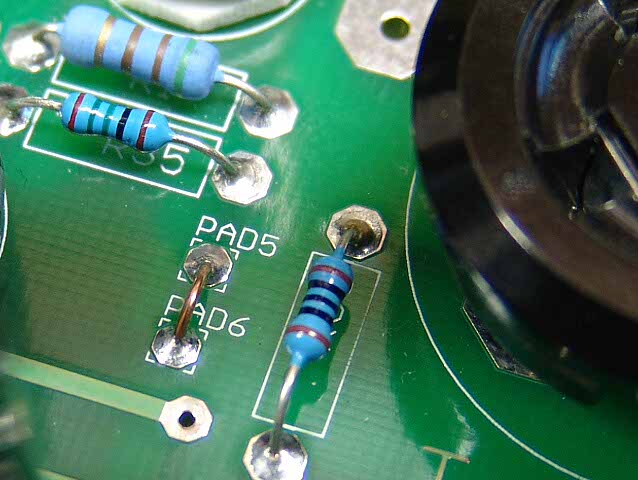 For use with 5 volt tubes, install a jumper from pad 5 to pad 6 as shown. This programs the voltage regulator to 5 volts.
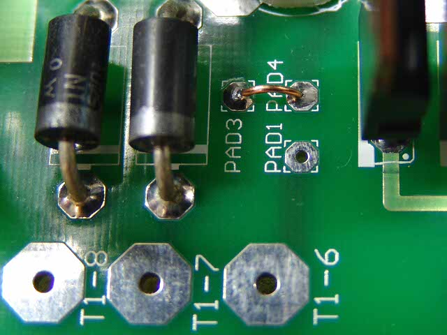 For 5 volts you must also put a jumper from pad 3 to pad 4 as shown. There is no connection to pad 1. This selects a full wave bridge configuration for the filament transformer.
2.5 volts (2A3, 45 and others)
 For use with 2.5 volt tubes NO jumper is placed in pad 5 or pad 6. Leaving this connection open programs the regulator for 2.5 volts.
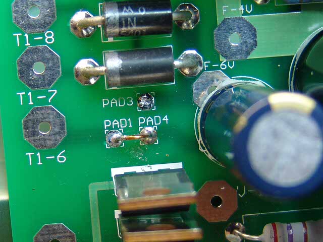 For 2.5 volts place a jumper between pad 1 and pad 4. This selects a full wave center tapped configuration for the filament transformer.
Some of you may have figured out that it may be possible to wire a DPDT switch up to these jumper pads to make the filament voltage switchable. Yes this is possible, and I have done it. I DON'T RECOMMEND THIS! Technically it works just fine. The problem happens when you put the switch in the wrong position with 2.5 volt tubes in the amp. Having a easily accessible switch makes it TOO EASY to do this. I have a nice pair of rare Canadian GE 45's with BLOWN FILAMENTS from doing this. I have also used the shunts from computer boards to make selectable filaments, this is also hazardous to expensive filaments.
Volume Control
This board may be built with a volume control on the board. It can also be built without it. Some users will want to mount the volume control off the board in a convenient location for their choice of enclosure. Other users may be using a preamp with a volume control. In either of these cases, you should skip these steps.
The types of volume control potentiometers available for PC board mounting are not available in vacuum tube friendly values, or their quality is not great. Therefore I have put large pads on the board so that a standard size volume control can be used. It can be mounted flush with the board, or on short wire standoffs slightly above the board. The volume control could be mounted below the board, however this requires crossing the outer wires over each other.