Amplifiers

There are two P-P designs currently under development. The “Small” one, now called the SPP, and the "Big" one, now called the Universal PP driver. The Small one has progressed to the "third prototype PC board" stage. It is currently going through my rigorous testing, and I have been using it for several experiments. I plan to take this design through to a production PC board, but it will not be ready until the 2nd quarter of 2009.

The circuitry is not all that unusual. I Have already been informed that it bears a resemblance to SY's "red light district" amplifier, and Morgan Jones "Bevois Valley" amp. The truth is that it is about as simple of a P-P amp that I could come up with that yielded good performance. All three of these amps look like descendants of the Williamson to me.

Why have I done "yet another version of this common design?" I have breadboarded countless variations of small P-P amps. Some used the 6AQ5 tube, and some used the 6BQ5 / EL84 tube. Every amp was evaluated for performance, simplicity, and most important, the ability to be assembled by builders of varying skill levels and work the first time. One of the main requirements was for a stable design that didn't require any component tweaking to make it work. This design worked out to be the best. I chose the 6BQ5 / EL84 tube mostly because that is what was requested in the email that I received. The 6AQ5 is cheaper but produces slightly less power, and a slightly different sound. I may produce a 6AQ5 version of this board if there are enough requests for it.

As usual the board can be wired for triode, UL and pentode mode. Provision for global negative feedback is available. It can be used if needed, and it is needed in pentode mode.

There have been the usual delays due to "trying to keep my day job" activities and Sherri being away for much of the year, but the most recent delays are for two good reasons. I got some $1 output tubes that may work in this amplifier, so I had to try them out. It turns out that a PC board change was required. During the development of the original board I built a hybrid amplifier that used a tube - mosfet "Darlington" connection for the output. Again a PC board change was needed. The changes have been implemented and a prototype board made. The board works as expected with 6BQ5's but I have not tested the other combinations yet.

I have included some photos below.

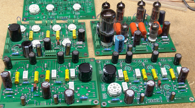
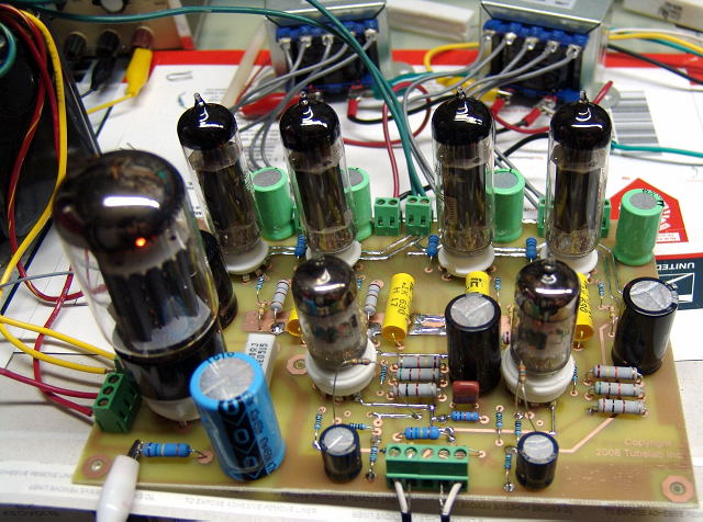
The first board, it hasn't seen any electricity yet.

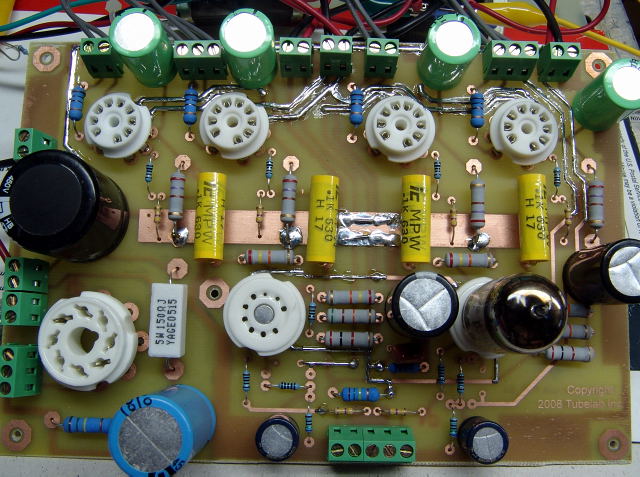
A careful look will reveal my first problem with this board. The driver tube on the right is installed. The driver tube on the left, won't fit in the socket! The holes for pins 2 and 3 are smaller than the pins on the tube. Next time I'll look more carefully at the sockets before installing them.

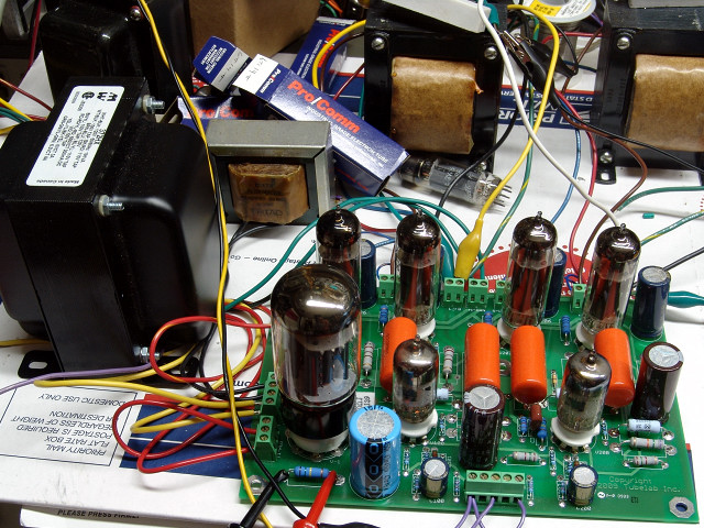
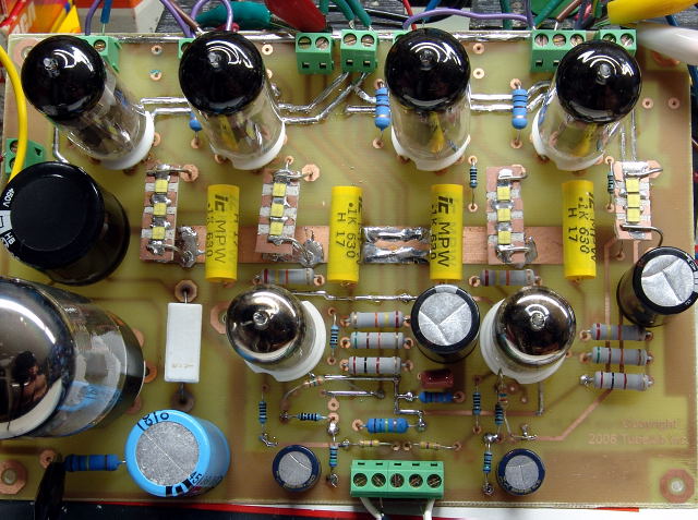
It is cranking some tunes here. The flying resistors are the GNFB resistors. I have not yet decided on an optimum value.

I added some much bigger transformers for much bigger sound.

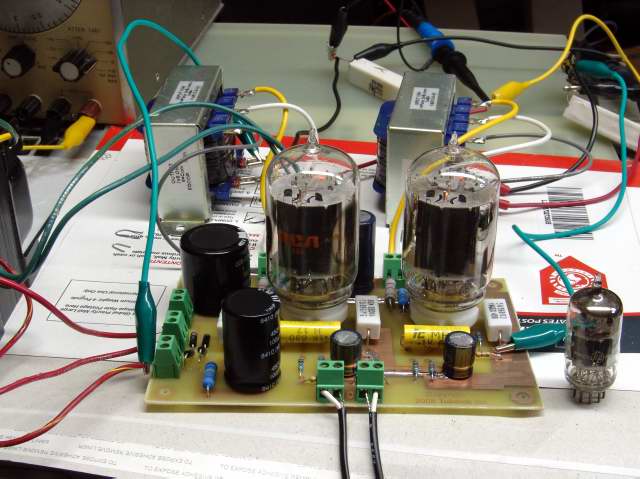
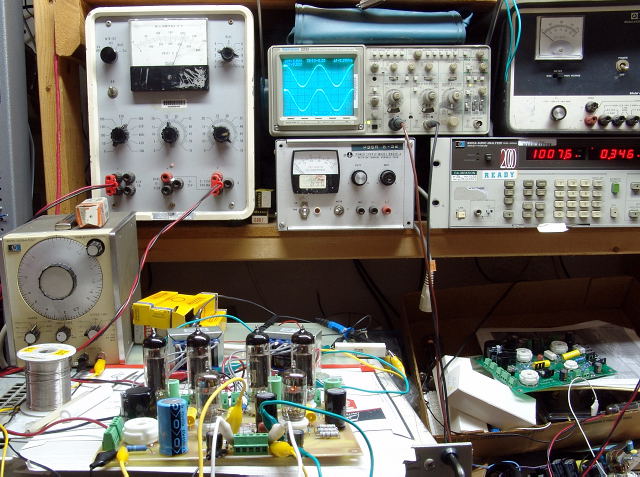
Board on test. Note the distortion number of 0.346%

SY convinced me to try this. The cathode resistors and bypass capacitors have been removed and replaced with LED's. In this case three special LED's were mounted in series on a heat sink material.The amp does indeed sound fantastic with LED's in the cathodes of the output tubes. I am looking for an off the shelf LED that will work here. It may be included in the design.

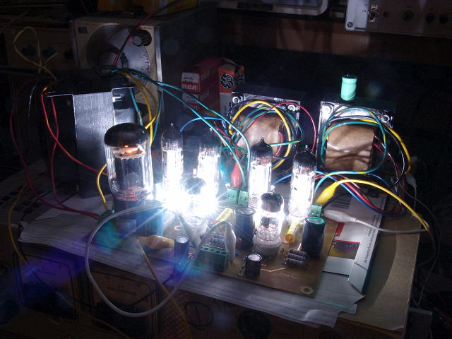
It can light up the whole room too!

Tubelab SPP Boards

The SPP boards are in house. This one has been kicking out the tunes for a few weeks now.

It has also been the subject of some extensive experimentation. In fact I decided to build another one, and then three more were assembled so that I could shoot all of the pictures for the manual.

All of the pictures have been taken for the manual and I am currently putting it all together on my laptop while travelling. I have discovered a few photos than must be redone once I return home. We have ordered the parts for a small parts kit which will consist of everything needed to populate the PC board. Both should be ready within two weeks of my return to Florida.

Spud SE

I have developed another future product, the Spud SE. This is a "really simple SE". It started out as an email conversation about "Spud Amps" and evolved into this. There was very little interest in this project until lately. In the past two months there have been a few questions about the availability of this board, unfortunately I don't have the time to work on it right now, and I am not sure that it would ever pay back the initial PC board design costs in today's economy. This one is on hold for now.

MiniTron

I got a lot of email about the MiniTron. Some called it cool, some thought it was criminal, most was positive though. Either way, the MiniTron and its derivatives will have to wait until I have more time. Circuit Cellar asked me to write an article about it for their magazine. That article is in the current issue of Circuit Cellar (Oct. 2009). I don't have the time right now to do any further development on the software. The MiniTron now sits, lonely, all alone in the closet, waiting for some attention.

The MiniTron amplifier was designed for entry into the Circuit Cellar / Microchip design contest. In a sea of microprocessor powered IC based gizmos this vacuum tube amplifier WON ONE OF THE CATEGORY PRIZES!!! It is featured in the Oct 2009 issue of Circuit Cellar magazine, and is currently on their web site.I will be posting much more information about this design in the coming months. You don't care anything about an amplifier that has more chips than tubes? I don't blame you, but this project has taught me a lot about the distortion producing mechanisms in vacuum tube circuits. I am using this information to design some radically new vacuum tube circuitry, that is silicon free, as well as some unique hybrid designs. Unfortunately the events outlined below have severely slowed down the progress. The amplifier you see above was completed in early October, and hasn't been touched since.

Progress has resumed slowly with the design of an all tube cathode follower amp incorporating some of the technology developed during the development of the MiniTron. A new page for this design will be created soon. One component of the MiniTron is the cathode follower amplifier, which still has its own page. The complete contest submission including schematics, source code, and design details can be found here:

http://www.circuitcellar.com/microchip2007/winners/MT2209.html

Tubelab SSE update

There have been a few questions related to the construction of amps. Many builders request an exact parts list with part numbers and transformer recommendations for the “standard configurations” It is impossible to cover all of the possible combinations, but I have added specific transformer and configuration information to the Tubes and Applications page. There have been numerous inquiries about a small parts kit for this board. I have decided to offer a kit containing all of the parts to populate the PC board. Most of the parts have been ordered and I should have everything some time in November.

Tubelab SE update

There have been far more questions about the Tubelab SE. The parts list has been modified to reflect the changes outlined below.

If you have a Tubelab SE and it is working OK, leave it alone. If you have any instability, or have experienced blown mosfets, make these changes. If you are starting a new build, or in the process of building one, make the following changes.

Increase the grid stopper resistors on the 5842 (R31 and R32) from 1K to 4.7K ohm. These resistors should be carbon composition if at all possible. The 5842 will oscillate if given the opportunity. The higher stopper resistor value will help. If you are using a volume pot on the board, make sure that the case of the pot is grounded. The cable from the board to the input jacks should be connected to ground on the PC board, and connected to ground at the input jacks. All ground connections to the chassis should be made at the input jacks. See the wiring diagrams for the Simple SE for details. The oscillation occurs in the 100KHz range which is inaudible, but may be heard as a hum or buzz. It can also cause the output tube current to rise unexpectedly.

R14 and R25 set the operating current for the mosfets. The parts list shows a value of 20K ohms. This is good for boards that operate from 275 to 325 volts of B+. Boards that operate from 325 to 360 volts should use 30K ohms. Boards that operate from 360 volts to 400 volts should use 36K ohms. This will reduce the dissipation at higher voltages. The B+ voltage may be considerably higher than normal during the time that the tubes are warming up. This is especially true with low cost power transformers. Voltages of 450 volts and higher have been seen, which combined with high mosfet current can lead to blown mosfets on power up.

C6 should be rated for the full B+ voltage, and the expected rise on power up. This means a 350 volt cap is OK for 45 amps that run at 275 to 325 volts. A 400 volt cap should be used if your B+ is from 325 to 360 volts, and a 450 volt cap is needed for boards that run from 360 to 400 volts. It is unlikely that a 100uF cap that will fit the PC board can be found in the higher voltages. It is OK to use an 82 or 68 uF cap.

New computer

My new computer is finally operational, and most of my applications and data have been migrated. Microsoft has decided not to offer anymore upgrades to the Front Page software that I have been using to make this web site. They now offer Microsoft Expression Web as the upgrade path. I purchased Expression Web and loaded on my computer. I tried to use it on my web site. It doesn't work with my site. Expression does not support the navigation structure built by Front Page, and tells me that my Web site was not built to current web standards. I bought a couple of books, and decided that this is not going to be easy. I am still using Front Page for now.

I have been on the road for almost every weekend so far this year. Most of this web update was written from the passenger seat of a car on my laptop. Some pages are still incomplete, but I decided to post what I have since it has been a while since the last update. Most of the SSE manual is complete, except for the wiring diagrams, parts list with vendor part numbers since I don't have internet access in my car, and the assembly pictures of my latest amps, since I haven't been home to take the pictures. I built (and documented) the Industrial amp shown above in December, and haven't had time to listen to it since then. I haven't touched a soldering iron yet this year either.

I have not yet figured out how to set up an internet shopping cart on my web page. It must be set up interactively on the server, and again, I have not been home to figure it out. I plan to begin listing the PC boards on Ebay as soon as the parts lists and wiring diagrams are complete. If my current work schedule does not change, this should be in a couple of weeks. My Ebay ID is Tubelab*com. There is nothing posted there currently.

I have fallen far behind in answering email. I thought that I could catch up over the holidays, but my planned two week vacation turned into 6 days off from work. I spent one to two hours per day answering email. During this time I received more email that I answered. I still have several hundred emails in my in box, and 5 or 10 come in each day. I have come to the realization that I may never catch up. All email from purchasers of my boards has been answered promptly. Much of the other email concerns PowerDrive. The PowerDrive cookbook page is not finished yet, but I have posted the first part. More email concerns the availability of the PC boards. They will be available shortly, and the ordering info will be posted here. Email that requires considerable time, like those asking me to design a special circuit, or modify or test an amplifier that I have never seen often does not get answered. I simply don't have the time to design one off circuits until I get caught up.

Many questions (e-mail and diyAudio forum) relate to the PC boards. I get questions that ask about the "SE board". I have no way of knowing which board you are referring to, since there are now two different SE boards. I have also received questions asking how to wire a DHT into the SSE board and vice versa. This is not really practical. Each board was designed and optimized for the type of tubes listed in the assembly manual. I simply do not currently have the time to assist with a custom design or application for these designs.

The most popular questions are," Where can I get a board" and "When can I get a board". I plan to offer the boards directly from an online ordering page on this web site. I have that option on my current hosting plan. I may also offer them from an Ebay store. I will do this as soon as the assembly manual is finished. Most of the manual is finished (all of the fun amp building stuff). I need to finish processing about 200 pictures and organizing all of the text. I have about 3 weeks worth of work at my present rate, but I can not predict the demands of my full time job, which have been considerable, and require 8 to 10 hours of sitting in front of a computer per day.

The progress will be posted here on this page, and ordering information will be posted here as well.

Thanksgiving

It has been over 1 month since I ordered my new PC. It is still in pieces, occupying my workbench. I returned the defective memory, but have not received the replacements. Two of the three shiny new PC boards shown above are impatiently awaiting assembly into amplifiers, but I have no bench space. The middle board already has a happy home in a new amplifier. I have not been here much anyway.

Last Thursday was the Thanksgiving holiday here in the USA. Traditionally it is spent with family. I drove to Tampa to celebrate Thanksgiving with my mom and brothers. The Friday after Thanksgiving has evolved into a major shopping event with half of America going to the shopping malls. This is a tradition that I do not choose to support, so I dropped Sherri and friends off at a mall near Orlando. A friend and I went to Daytona for the Turkey Rod Run. A 5 day celebration of all things automotive, where I spent 5 hours before going back to Orlando to pick up Sherri, and return to Ft Lauderdale. A page full of pictures has been added to the automotive pages.

Saturday and Sunday was spent working on the SSE assembly manual, and updating this web site. I have added more of the assembly manual, with more to come after it has been proof read by a few others.

Monday I returned to work, and was rewarded with another "must be done before years end" project. This means more days like today, 11 hours in front of a computer.

Tubelab SSE Manual

I have uploaded parts of the Tubelab SSE manual. Pages that I have had the time to finish, proof read, and have an associate use to assemble a board are posted. Much of it was written on my laptop in the passenger seat of a car. I have been away for 5 of the last 6 weekends. I will be away for the next two weekends also. I plan to finish most of the manual during the traveling time. If all goes well the shopping cart will go live during the last week of November.

Because I wrote most of the assembly manual while traveling, there are probably errors that we didn't catch. If there are any, please e-mail me and I will fix them. I have fixed the ones that I received e-mail about (mostly wrong pictures). Please e-mail me if anything is not clearly understandable.