Table of Contents
- Getting Started
- Resistors
- Tube Sockets
- Connectors
- Capacitors
Semiconductors
Semiconductors
The Tubelab SPP’s original design did not incorporate any semiconductors. The typical EL84 build would not use any, so there are no provisions for installing semiconductors in this board. After the second iteration of the PC board was completed and the prototypes had arrived from the PC board house, I realized that there are two cases where a solid state rectifier would be advantageous. There may be builders on a budget that wish to use a power transformer that does not have a 5 volt filament winding. This is a possible build option with EL84 tubes. The 6CW5 tubes operate at a lower B+ voltage than the EL84 tubes, and consume more current. The 6CW5 version of the SPP consumes more current than the common rectifier tubes (5AR4, 5U4, 5Y3, 5R4,etc) can safely deliver. Solid state rectifier diodes are needed in a 6CW5 amplifier.
For these reasons I have illustrated a method to install solid state rectifier diodes in place of the rectifier tube. Two diodes are used. They will be soldered into the PC board in place of the octal socket normally occupied by the rectifier tube. This requires placing two wires in the same hole for one of the pins. The 6CW5 tube requires the use of 3 amp diodes which have thick leads. In some cases two of these wires may not fit in the PC board hole for pin 8 of the tube socket. I solved this by gently squeezing the leads flat with a pair of pliers before inserting them. Twisting or soldering the wires above the board so that only one wire goes into the hole is acceptable also.
The diodes are polarized and must be inserted in the proper direction. Incorrect assembly may result in blown fuses or worse! The diodes may be installed on either side of the PC board. Photos for both options are shown.
Top Side Assembly
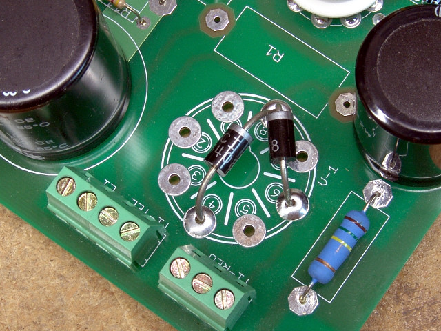 Install two diodes as shown. The cathode end (with the band or stripe) for both diodes MUST go into the hole for pin 8. The anode end (no stripe) of one diode goes into the hole for pin 4, and the anode end of the second diode goes into the hole for pin 6.
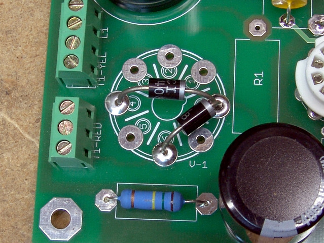 Another view.
Bottom Side Assembly
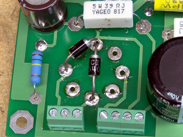 Install two diodes as shown. The cathode end (with the band or stripe) for both diodes MUST go into the hole for pin 8. The anode end (no stripe) of one diode goes into the hole for pin 4, and the anode end of the second diode goes into the hole for pin 6. Verify the correct pins before soldering.
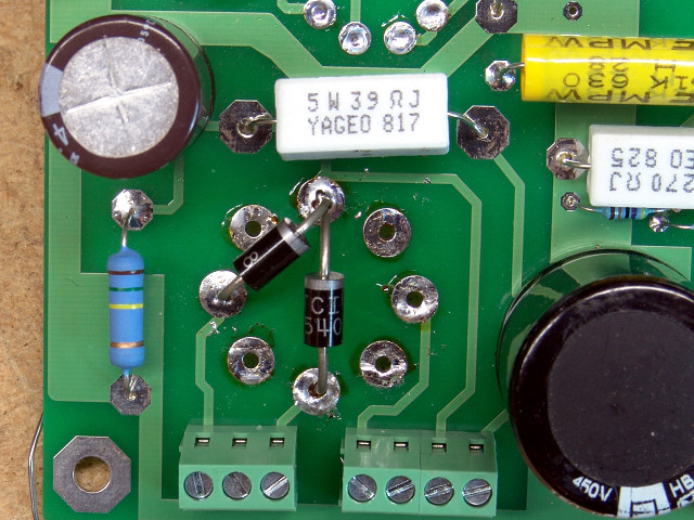 Another view.