Table of Contents
- Getting Started
- Resistors
- Tube Sockets
- Semiconductors
- Capacitors
- Final Assembly
Checkout
- Setting the Bias
- Enclosures
Checkout
Preparation for Checkout
In this step you will connect the transformers up to the board temporarily in order to power up the board. This is done because the transformers will probably need to be disconnected from the board for final mounting. If the final mounting position allows full access to the board it may be possible to mount the board before proceeding to the checkout page.
You need a clean work surface with enough space for the board, the 3 transformers, 3 multimeters, a power strip and all of the associated wiring. If you want to perform a complete listening test, you will need speakers and a CD player or other source. These should be located out of the way with the wires and interconnects leading into the working area. There must be access to the CD player in such a way that you can't touch the CD player and the board at the same time. This is an unsafe situation. You should never use your good speakers to power up a new amplifier. If there is a problem the speakers could be damaged.
Initial Checkout
This page is still being updated. I lost the original. I recovered these pictures form the dead hard drive. I had to build a new board to shoot new pictures. The board shown below was sold a few months ago. Many pictures are missing and being re shot with a different board. Each one of my boards have slight differences. Please ignore the differences and concentrate on the topic being displayed.
There are two ways to test a new board. You can make temporary connections from the board to the transformers (and choke if used). Test the board, and then remove all of the connections, mount the board in its final enclosure, reconnect everything and test again. OR, you can wait until everything is mounted for the checkout. Each method has its advantages. Which is right for you? That depends on how confident you are, and how accessible the parts on the board are in its final enclosure. Keep in mind that bare board testing is inherently dangerous due to all of the exposed electricity.
For these pictures the board was set up on the bench using temporary connections. I usually do this with all of my boards, since I tend to build 2 or 3 at the same time, then put them aside for later assembly into an amplifier. I want to make sure that I have known good boards in stock for quick assembly into an amplifier, or for when I get the urge to experiment on one!
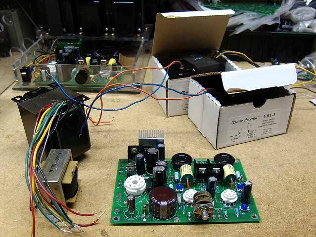
Here a freshly assembled board, the power transformer, 2 output transformers, and a choke (optional, but have it ready if you intend to use it) are gathered on a clean work surface. You may notice that the Tubelab SE in the background is missing its rectifier and output tubes. That is because I am going to ues them to test this board. That way I am using known good tubes.
Connect the transformers and the choke to the board. Do not install any tubes yet. The pictures below were taken after the board was operational (all I have at this moment) It is shown to illustrate the connections. Do not install any tubes, or power the board up until instructed to do so.
Here is a photo showing the connections to the power transformer. R4 has been removed and an external choke is connected in its place. (blue and purple wires). The white wire in the center of the front of the board goes to the GROUND terminal on the power cord receptacle. THIS IS VERY IMPORTANT! If your power transformer has a ground wire connect it to the power receptacle also. The output transformer connections are made in a similar manner although they are not visible in this photo.
Connect a voltmeter across R30 (the red and black mini grabbers in the foreground). Set this meter to its highest DC voltage range. This meter reads the B+ voltage. It may be useful to label it B+. During All subsequent tests leave this meter in place. Use this meter to check for presence of B+ voltage, but do not rely on it as the only means to verify that a board is safe to touch.
Connect another voltmeter across R7. Set this meter to its highest DC voltage range. This meter reads the B- voltage. It may be useful to label it B-.
Put another voltmeter across the filament supply for the output tubes. This is usually easiest at the tube socket itself. It may be useful to label it Filament.
Power the board up with no tubes in it. Verify that the filament voltages are correct. Then check the negative voltage supply. The B+ voltage may be slightly negative at this point. This is normal. Power OFF the board. Do NOT touch the board for 5 minutes after the power is disconnected. The negative voltage should decrease to a low value within a minute or so.
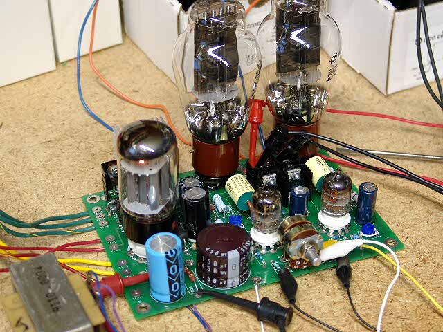
Next, put in a rectifier tube. Power up the board. After the rectifier tube warms up you should have B+. Power OFF the board. Do NOT touch the board for 5 minutes after the power is disconnected. The negative voltage should decrease to a low value within a minute or so, however the positive ( B+ ) voltage will decay at a slower rate since there is a light load on it with no tubes in the board.
You will need to measure the voltages at various points on the board in the following steps. If you only have 3 meters, leave one on the B+ voltage and use the other 2 for the individual tests. The meter on B+ is a quick indicator of circuit health.
Put a meter from the grid of the output tubes to ground. One meter for each tube. Power up the board. Each meter should read a negative voltage. With ONE HAND BEHIND YOUR BACK carefully adjust one of the bias pots (R12 or R23). The negative voltage for the corresponding output tube should change. Set it to the most negative voltage, and then adjust the bias pot for the other channel. Set them both to the most negative voltage. Power OFF the board. Do NOT touch the board for 5 minutes after the power is disconnected.
Next, put in the 5842's. Put a meter from the plate of each 5842 to ground. The plate is easiest to access by clipping the positive meter lead on to the coupling cap lead closest to the 5842. The cathode pots should adjust the plate voltage on the 5842's. Set them to about 175 volts (not critical). The pots were added because of the wide variation in 5842's that I saw. Power OFF the board. Do NOT touch the board for 5 minutes after the power is disconnected.
Connect a load to the amp, speakers or resistor. It is wise not to use your good speakers during initial testing. Finally, clip voltmeter leads across the 10 ohm resistors in the plate supply of each output tube (R18 and R29), put in the output tubes, and power the amp on. The tubes should draw no (or very little) current. After the amp has been on for a few minutes, slowly adjust the bias pots to raise the output tube current to the desired value. There will be some interaction, since the supply voltage drops under load. Let the amp run for a few minutes and watch the output tube current. Some tubes will creep upwards for a while, especially new ones. Power OFF the board. Do NOT touch the board for 5 minutes after the power is disconnected.
Connect a signal source up to the amp. I have used clip leads to connect the amp up to a CD player for temporary connections. These are visible in the photos above.
Power the amp ON. Now you can apply a signal and listen. Leave the meters in place for at least the first hour of operation. Watch the tube current and the B+ voltage carefully during the first few hours of operation since some tubes will creep upwards over time. Reset the tube current if it changes by more than 1 or 2 mA in the first hour. If it has increased, set it on the low side, since it is likely to increase further. Power OFF the board. Do NOT touch the board for 5 minutes after the power is disconnected.
Complete the assembly into the chassis or cabinet. Reconnect the 3 meters (B+ and tube current) before powering up. Power the amp ON and test for proper operation.
Recheck the tube current after about 10 hours of operation.