The output transformer has the toughest job in a vacuum tube amplifier. It must transform the high impedance signal at the plate of the output tube to a low impedance signal for the speaker. Ideally this happens for all audio frequencies, at all power levels from zero to full power, without distortion or phase shift. No transformer is perfect, not even close. Even the best transformers will saturate at high power and low frequencies. Transformer saturation yields a particularly nasty sounding form of distortion. At low power there is a threshold effect where for very small input signals there is no output signal. This (and the saturation effect) is due to the nonlinearities in the cores magnetic curve (BH curve). All transformers exhibit an excessive phase shift at frequency extremes. This will cause a feedback loop to go unstable if feedback is used. A hysteresis effect is also present.
It has been my experience that in both hi-fi and guitar amplifiers the output transformer has the greatest effect on the sound of the amplifier. The transformer's characteristic sound is also determined by the speaker that it is connected to. I have tried several sets of transformers in my 300B push - pull amp. The UTC LS57's (I got them at a flea market) sound great with an old pair of AR speakers but are so bright that they are painful with my Yamaha NS10 speakers. The amp now uses a pair of surplus transformers that sound great with the NS10's. The transformer's characteristic sound becomes more pronounced as it is operated at high power levels. This is one of the reasons for the classic sound of an old Fender guitar amp. The old Fenders use a transformer that is too small to be considered for hi-fi operation. This causes a unique type of distortion when overdriven. This sound is a mix of tube distortion and transformer saturation.
It is possible to design a chopper circuit to "chop" the audio signal at a constant frequency well above the audio band such that the transformer operates at a constant frequency. Actually there are modulation effects that produce a band of frequencies on either side of the chopper frequency that must be considered. This analogous to amplitude modulation of the chopper frequency (carrier) by the audio signal (modulation signal). The modulated signal then passes through a transformer which is designed for operation at the carrier frequency. The signal then passes through a synchronous detector to reverse the chopping.
Why would you want to do this? Well for one this "transformer" will work with DC. The frequency response literally extends to zero on the low end. The high frequency response is limited by the choice of chopper frequency and by limitations in the transformer itself. Threshold, hysteresis, and phase shift are non-existent. Saturation is also reduced. The dynamic range is much greater than a conventional transformer.
OK, what does it sound like? I bread boarded a single ended amp (two Chinese KT-88's in parallel) on Tubelab 2. The amp was only together for a few days since I dismantled Tubelab 2 to build Tubelab 3. The bass is incredible. Techno, dance music, loud rock, no problem. The bass sounds like a powerful solid state amp. The amp sounds clean and doesn't seem to have a characteristic sound. This will be one of the first projects to be built up on Tubelab 3. I have provided a few details below for those who have the urge to fry a few FETs.
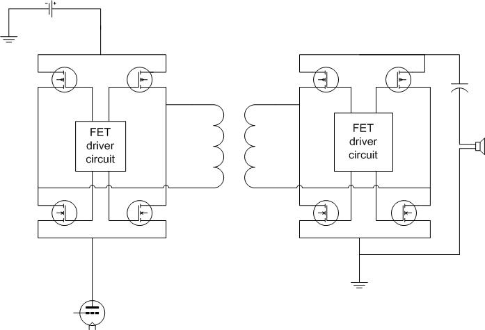
The transformer shown in the diagram is a high frequency transformer similar to those used in switching power supplies. The transformer used in the prototype was taken from a PC power supply. The chopper frequency is well above the audio range. The prototype runs at 70KHz. Two phases of drive are required, dead time is needed since the FETs require time to turn off. The FETs on the primary side must be chosen to handle the tube's B+ voltage. We tried several IR and On Semiconductor FETs. They all will blow up if the timing isn't right, and the timing varies with the type of FET being used. The FETs on the secondary side should be chosen to handle the speaker current with low loss. We used On Semi 20N06 and 20P03 FETs, they don't blow up. The FET driver circuits are definitely the hard part in this design.
If you choose to experiment with this design be prepared to blow up a lot of FETs. I blew up about 10 FETs in two days. The driver circuit will be posted when I am happy with it.