Table of Contents
- Getting Started
- Resistors
- Tube Sockets
- Semiconductors
- Capacitors
- Final Assembly
- Checkout
Setting the Bias
- Enclosures
Setting the Bias
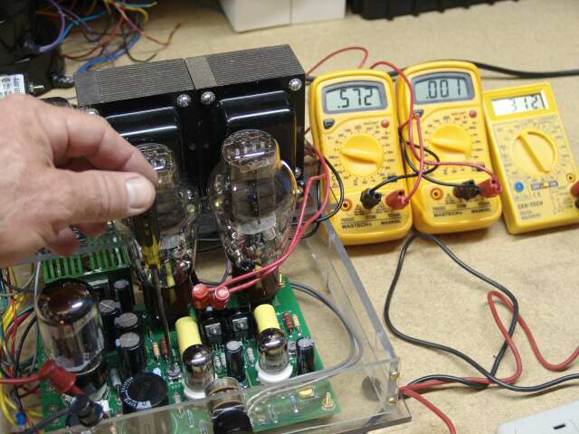
Since these multimeters cost less than some of the parts used in this amplifier, it makes sense to use more than one. Hook them all up to the amplifier BEFORE turning on the power, and then simply stand a safe distance away, and flip the switch. No fingers (or any other body part) should be near the electricity. When you have to make adjustments, then one hand, on an insulated screwdriver goes near the amplifier. The other hand (and the rest of your body) does not touch ANYTHING. This procedure makes electric shock very unlikely. Below you will see three meters connected into a Tubelab SE amplifier. The large meters indicate the bias current for each channel and the small meter indicates the B+ supply voltage. It is always a good idea to have a meter on the B+ supply when powering up a new circuit. It gives a quick indication of circuit health, and an indication of how much stored charge is left after the amp is turned off. Here the bias is adjusted with one hand, and little chance of being shocked or burned. It is easy to tell that the left channel is set to 57.2 mA, the right channel is still zero (not set yet) and the B+ is 312 volts. For this amplifier design, I would consider 3 meters the minimum for initial setup. Full details on initial testing of the Tubelab SE amplifier are furnished on the CD that is included with the board. This can be accomplished with 3 meters. They can all be the $4 type if you desire.
There are 4 adjustments that need to be made. If you have 3 meters, do the output tubes first as shown in the photo below. Place one meter on the B+ (R30), one on the right channel shunt (R18) and one on the left channel shunt (R29). If you have a fourth meter, connect it to the negative bias voltage (R7) as shown below. After the bias is set, power down the amp, remove the power cord, and wait for it it cool and discharge. Then move the meters that were across R18 and R29 to C9 and C11 as shown a few pictures later. The B+ meter should remain on the B+ bleeder (R30). Power the amp up and set the driver plate voltages as shown.
If you have 5 meters connect them up to the B+, output tubes (R18 and R29), and the driver tubes (C9 and C11). Power the amp up, set the output tube bias first, then set the driver tube voltage. If you have a sixth meter, connect it to the negative bias voltage (R7) as shown below.
I usually leave the meters in place for the first few hours of use. This can spot potential problems. The bias current for the output tubes often drifts around during the first few hours of use, particularly with new tubes. If you only have 3 meters, monitor the B+ voltage, and each output tube bias shunt.
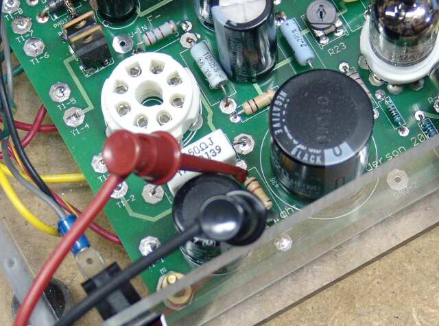
Below we attach a pair of clips to the right channel bias shunt (R18). The tubes have been removed so that they don't get in the way. These leads go to one meter.
Here the clips are applied to the left channel bias shunt (R29). These are connected to a second meter.
Here clips are applied across R30 which is the main B+ bleeder resistor. These are connected to the third meter.
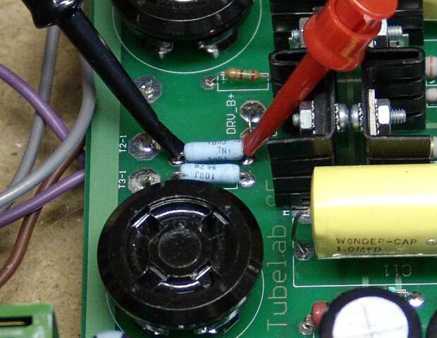
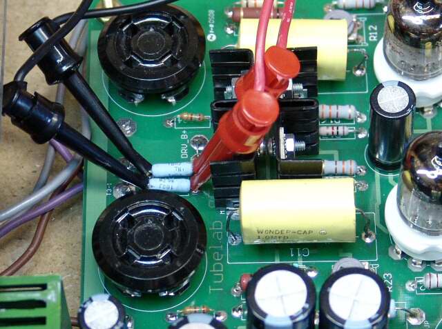
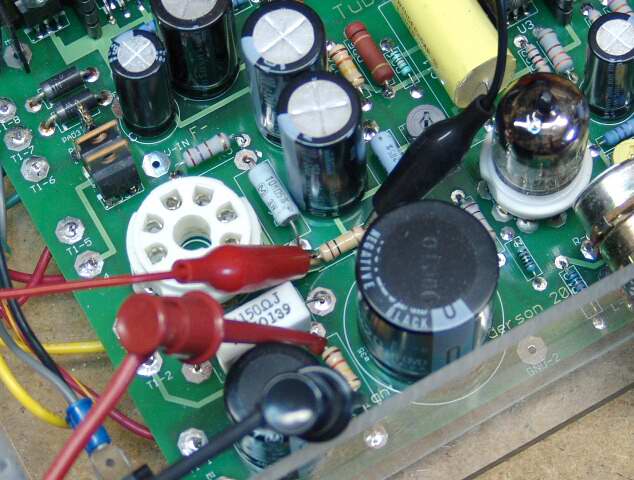
Now two more sets of clips have been attached. these monitor the drivers plate voltage, which must be adjusted. The left channel meter connects from C11 to GROUND. The right channel meter connects from C9 to GROUND.

If you have an extra meter, you should monitor the negative bias voltage. Here the clips are attached to the B- (bias) bleeder (R7). I ran out of Mini - Grabbers, so I used small alligator clips.
Now the tubes can be installed and the amp connected up
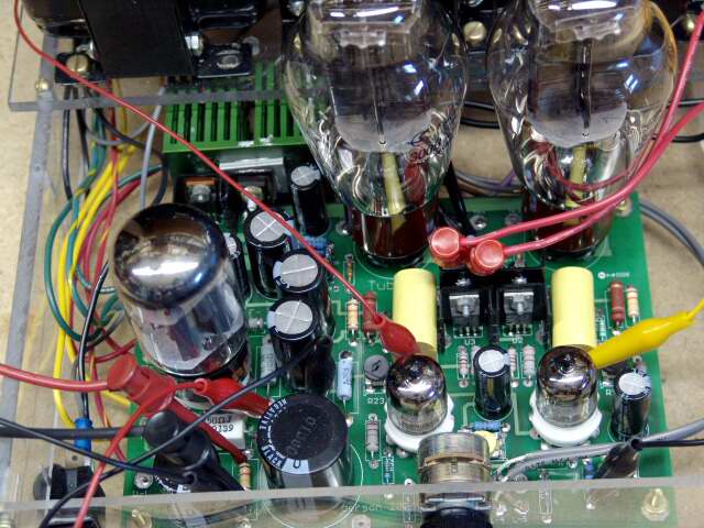
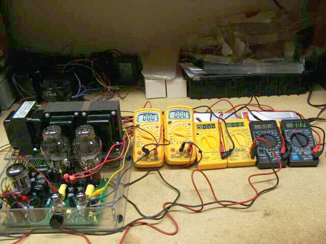
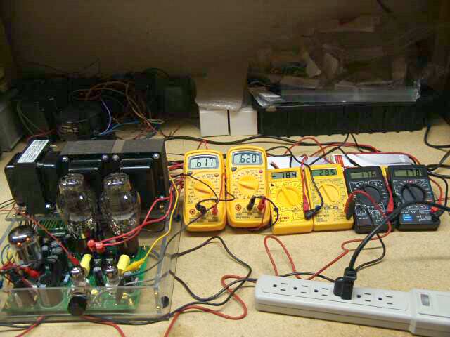
Next each set of leads gets its own meter. The power strip is the master power control here since it is easier to get at than the amplifier's power switch. All of the excess wire from the meter leads is gathered up behind the amp and the meters. The cheap meters are propped up with boxes so they can be easily read. Anything that is not needed is removed from the immediate area.
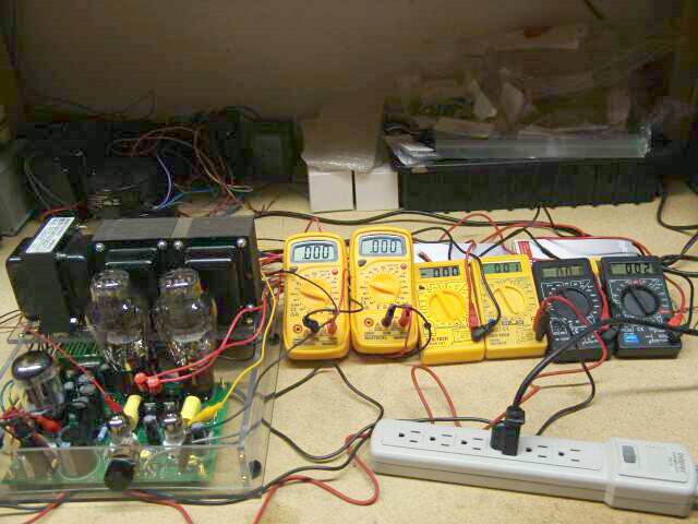
Now it is time to flip the switch, since this is a working amplifier, nothing bad is going to happen. The meters show left channel 300B bias is 61.7mA, right channel 62mA. Main bias voltage -184, main B+ voltage 285 volts. The left 5842 plate was set to 176 volts. The right 5842 plate is 178 volts.
Here the power strip has been turned OFF and the meters all read near zero. After all meters are reading less than 5 volts, it is safe to approach the amplifier.
After the voltage had decayed to very low values, the power strip, and the power cord were removed from the work bench. This makes accidental turn - on impossible.