Table of Contents
- Getting Started
- Resistors
- Tube Sockets
- Capacitors
- Semiconductors
- Connectors
Wiring Diagrams
- Checkout
- Enclosures
Wiring Diagrams
This page contains pictorial wiring diagrams for the connections from the PC board to the external components. In many cases this can be completed without soldering. Wiring for each external component is covered. Several popular hookup configurations for the completed amplifier are presented as well.
The following diagrams illustrate how the individual external connections to the PC board are made. These are all shown as viewed from the top of the PC board. This is how everything would look if you were using above the chassis mounting.
I have added two diagrams as viewed from under the chassis at the bottom of this page.
The optional components (standby switch, rectifier switch, choke, supplemental capacitor, UL / triode switch, and CFB switch) can be used individually or in combination.
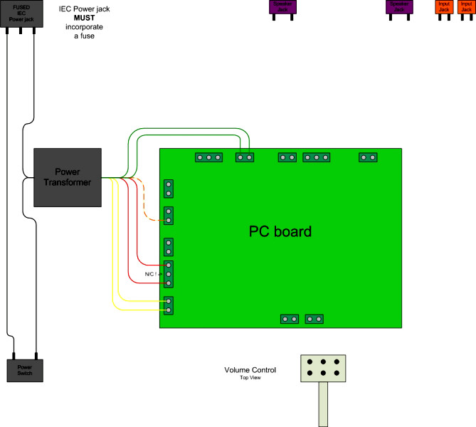
The above diagram shows how to connect up the power transformer. Most power transformers use this standard color code for the wires. The yellow wires are the 5 volt rectifier filament winding. They are connected to the terminals marked "T1-YEL". Make no other connection to these wires or terminals. This circuit is connected to B+ and can not be used to power anything else. The red wires are the high voltage AC. They are connected to the terminals marked T1-RED. The center terminal on this connector is not used. Make no connection to this terminal. The red and yellow wire is the center tap for the high voltage winding. It is connected to either of the T1-red-yel terminals, or to the standby switch if one is used. The green wires are the 6.3 volt filament wires. They are connected to the T1-grn terminals. These terminals are located on the rear of the board to keep the AC away from the sensitive areas of the PC board. The black wires are the primary connections. The standard wiring connections are shown. This diagram requires the use of a fused IEC power receptacle. The switch must be rated for operation on the power line in use in your location.
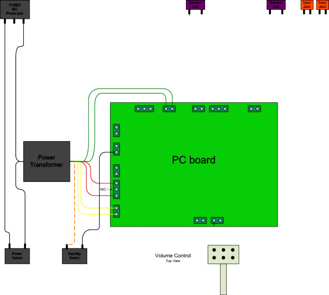 Adding a standby switch
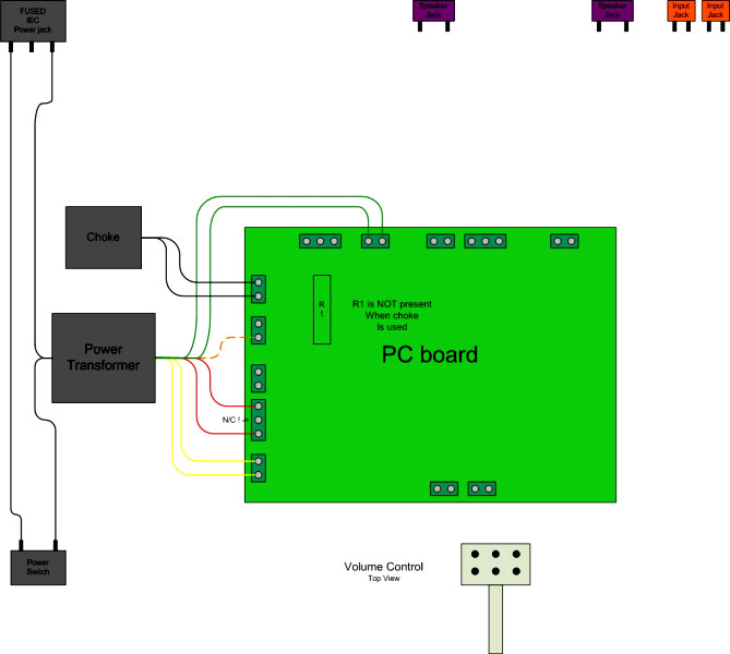 Adding a choke in the power supply
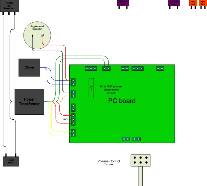 Adding a supplemental capacitor to the power supply
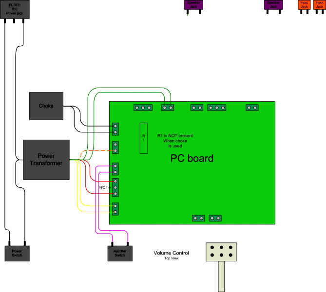 Adding a switch to choose SS or tube rectifier.
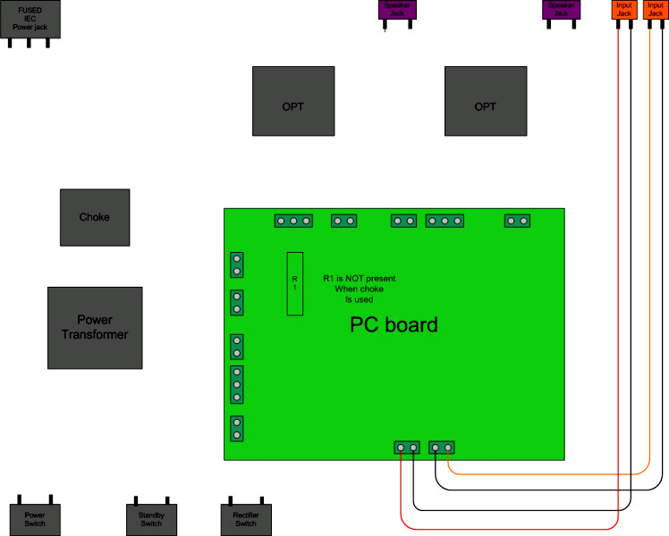 Input connections without a volume control.
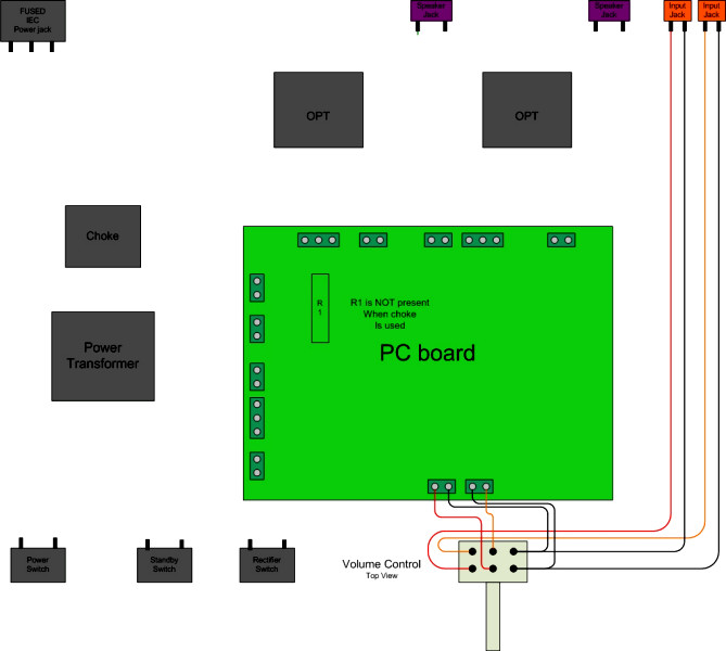 Input connections with a volume control.
Grounding
The grounding is very important to make the amplifier safe and eliminate hum. Any metal object that can be touched MUST be connected to the GROUND terminal on the power receptacle. VERIFY this connection with an ohm meter BEFORE powering up the amplifier. A shorted transformer could be LETHAL if not grounded, there could be hundreds of volts on the case. Leaky insulation in a transformer, or capacitor could put lethal amounts of electricity on the case, the volume control, the speaker wires, or the input jacks (electrifying the case of your CD player). Check all exposed metal for less than 1 ohm of resistance to the center terminal of the power connector. Do not operate the amplifier until this is verified!
A separate ground wire from each transformer case, capacitor case, and the volume control housing, to the GROUND terminal MUST be run if a non conductive chassis is used. If a metal chassis is used It should be securely grounded. The best place to make this ground is at the input connector. To avoid hum, this should be the only connection to the chassis. All metal objects (transformers, supplemental cap, choke, volume control, etc) should have a good paint free contact with the chassis. Again, verify this with an ohm meter before using the amp.
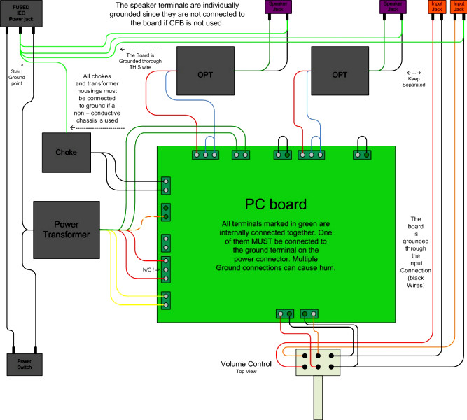
All of the circuit board terminals colored dark green in the above diagram are connected together internally on the PC board. Only one path to GROUND is needed. Generally multiple paths can cause hum. In this diagram the circuit board gets its ground through the input wiring. Cathode feedback is not used in this diagram, so the speaker terminals MUST be individually connected to circuit ground. This is shown in light green. Connections to the power, and output transformer cases are not shown in this diagram (the diagram gets too dense) but MUST be present.
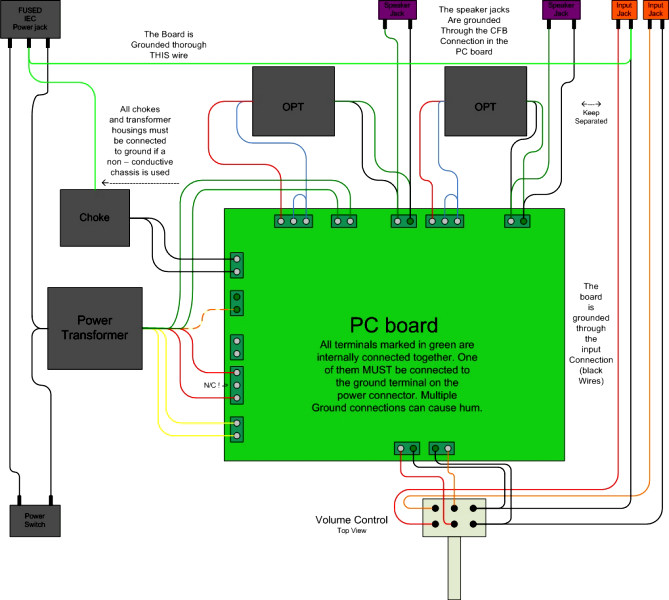
Cathode feedback is used in this diagram. The secondary of the OPT's are connected to ground on the PC board so a separate connection is not needed. Note the reverse connection of the output transformer secondaries. This is needed on many OPT's to get NEGATIVE feedback to the cathode of the output tube. If unsure of your particular OPT's try wiring the secondaries each way (swap the two secondary wires, leave the primary alone). Chose the connection that produces the lowest volume.
Complete Wiring Scenarios
This section shows connections for a complete amplifier. Several popular configurations are shown.
If you take some time to study these diagrams, you will come to the conclusion that you can wire your amp up initially according to the basic triode connected amplifier shown in the diagram below. Perform all of the initial testing, get it all working, and enjoy it for a while. Then you can add any of the options shown on this page, often with only a screwdriver and wire strippers! This is by design. It is recommended that you start with the simplest configuration first, then add all of the optional stuff. This is the way that I build an amp. Often all of the switches, and supplemental parts are mounted, I just don't connect it all up until the basic amp is working. This makes the wiring a little easier to handle.
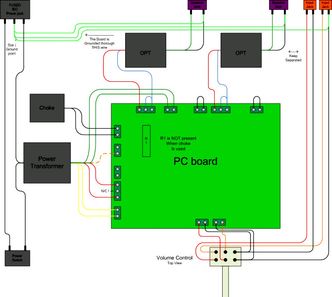 A basic Triode connected amp without feedback. A power supply choke is added. This is the most common configuration for a clean basic amplifier. If a choke is not desired, see the next diagram, and use the OPT wiring from this diagram.
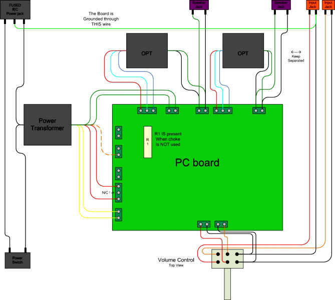 This diagram shows a UL connected amp with cathode feedback. I find that UL and CFB go well together, but you can use UL without CFB. A choke is not used in this diagram to illustrate the connections. A choke is recommended for all but the most basic amplifiers.
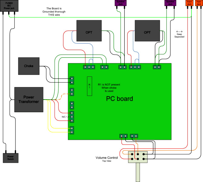 This diagram shows Triode mode with CFB. I use triode mode without CFB for most amps, but CFB works wonders for cleaning up the sound of budget OPT's. It works well with the $18 Edcors and the Hammond 125 series.
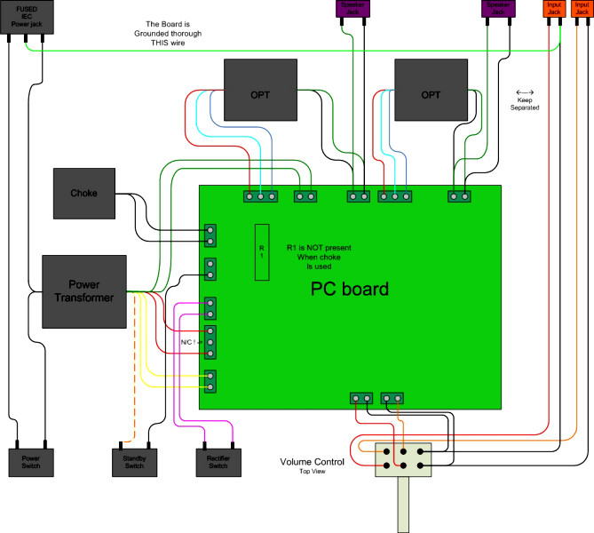 This is the diagram for UL with cathode feedback. A power supply choke, a standby switch, and a rectifier switch have been added. This is also a common configuration.
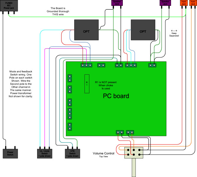 Here we add a UL / triode switch (left) and a CFB disable switch (right) The diagram would get too complex if all of the wiring was shown, so some of the wiring that is shown in the previous diagrams is not shown. For simplicity, only the left channel is shown. The switches used should be DPDT having 6 terminals. Wire the right channel up exactly the same way as the left channel.
Start with the basic triode amp, get it all working correctly. Then add the choke, the supplemental power supply cap, the rectifier and standby switches (if desired). Then add the UL / triode switch and (or) the CFB switch. Any or all of these options can be added individually or in combination. I recommend making only one change at a time, and retesting the amp. This will uncover any problems before they get too hard to find.
The following diagrams illustrate how the individual external connections to the PC board are made. These are all shown as viewed from under the chassis using a PC board that was assembled for under the chassis mounting.
 This is the basic hookup for an UL amp with CFB. I added it to aid in the assembly of an under the chassis amp.
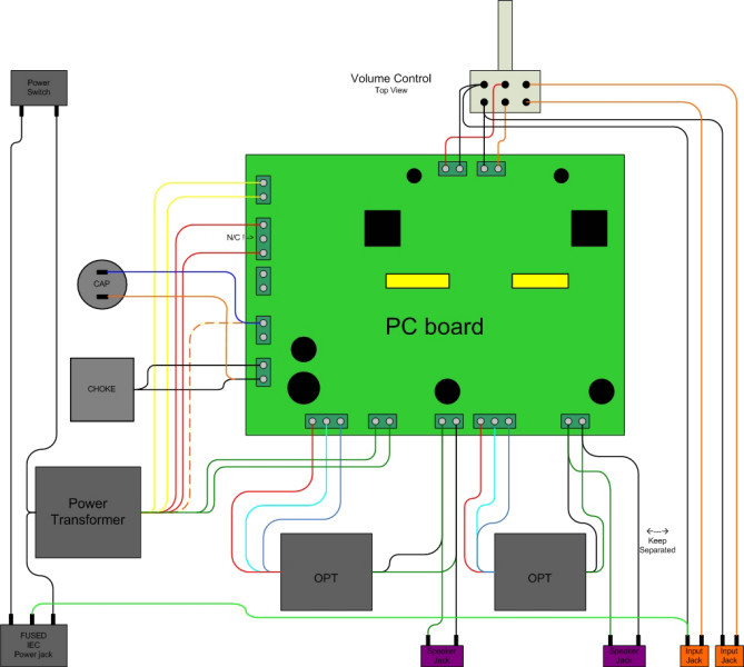 Here an optional choke and supplemental capacitor are shown.