Table of Contents
- Getting Started
- Resistors
- Tube Sockets
- Capacitors
Semiconductors
- Connectors
- Wiring Diagrams
- Checkout
- Enclosures
Semiconductors
Some of the semiconductors used on this board require heat sinks for proper operation. Do not attempt to operate the board without the heat sinks in place. This will cause component damage. The heat sinks on the CCS IC’s have the full B+ voltage on them DO NOT TOUCH THEM to see if they are hot when the amp is on! The tabs on the Hex FREDs are also carrying high voltage. This is one of the many reasons that the board should not be operated without a protective enclosure.
![]() The photo shows the semiconductors used on this board. From left to right, constant current source IC's, Hex FREDs, and mounting hardware. Above them are the heat sinks required for the CCS IC's.
The photo shows the semiconductors used on this board. From left to right, constant current source IC's, Hex FREDs, and mounting hardware. Above them are the heat sinks required for the CCS IC's.
As with the capacitors and the connectors, these components can be mounted on the top or the bottom of the board. Like the electrolytic capacitors, the semiconductors have a polarity. Because of this the installation procedure changes depending on which side of the board the component is installed on. Pay particular attention to the direction of the bends in the component leads. This changes depending on the side of the board.
![]()
There are two types of semiconductors used in this amp. The FRED diodes are shown in the bottom of this photo, and the 10M45 CCS IC is shown at the top. The CCS IC's are shown attached to their heat sinks as used in the conventional (top side) assembly method.
IMPORTANT!
Below are the assembly instructions for conventional top side assembly, inverted bottom side assembly, and an alternate assembly method for the diodes D1 and D2 that is useful for all types of amplifier construction. Please read all of the construction methods and choose the one that is best suited for your amplifier design. I prefer the alternate diode assembly method, because it reduces the possibility of touching the tabs on the diodes. The metal tabs on the diodes are connected to the high voltage winding on the power transformer. Accidentally touching one of them could ruin your day ----- PERMANENTLY.
Installing the Semiconductors (top side assembly)
In this method the semiconductors are mounted on the top side of the board. This allows the best air flow, but ALL of the semiconductors have potentially lethal voltages on the exposed metal surfaces. If you mount the semiconductors on the top of the board, you MUST provide a barrier so they can not be touched by the user. This is usually the amplifiers enclosure.
There is an alternate mounting method for the diodes that places them on the top side of the board laying down. This works with most mounting schemes, so please read it (bottom of the page) before starting, and use it if you feel it will work for you.
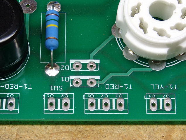 We will start with the FRED diodes D1 and D2. They are the semiconductors with two leads. For ease of assembly install D2 first. They go in the board so that they match the outline screened on the board. Installing a diode backwards will cause a very short unhappy life for the diode, C1, and possibly the power transformer!
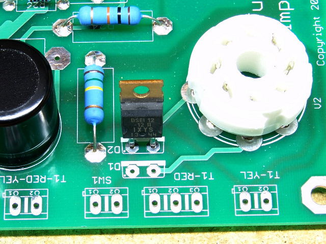 Insert D2 as shown.
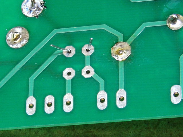 Bend the leads slightly to keep it from falling out.
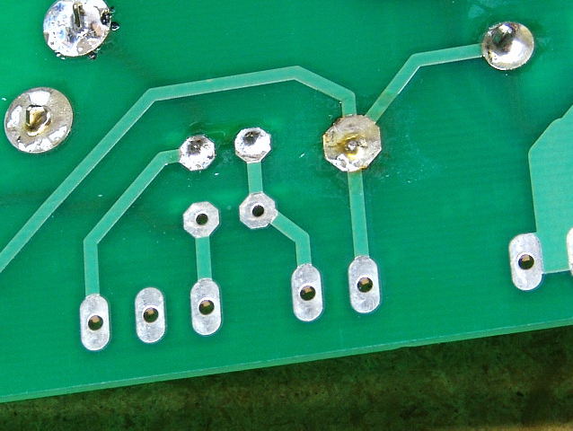 Solder it in place.
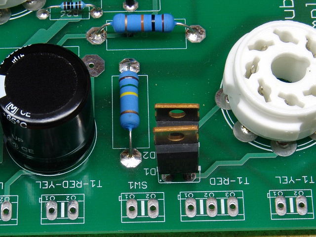 Repeat with D1. You should have two diodes in the PC board and they should look like this.
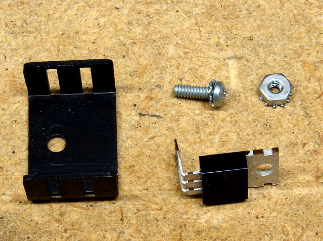 We will now install the CCS IC's U10 and U20. Using needle nosed pliers, bend the leads of the IC's as shown. The leads should be bent right at the point where their width decreases. Do not put any stress on the area where the leads enter the plastic. The leads should not be bent in this area.
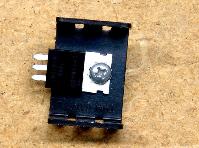 The IC should be attached to the small heat sink with a #4 screw and lock nut. The hole in the heat sink is not in the center. Assemble the IC to the heat sink as shown so that the leads are closest to the edge of the heat sink. Verify that the assembly will fit into the PC board and tighten the nut. Assemble both IC's to their heat sinks. See the photos below.
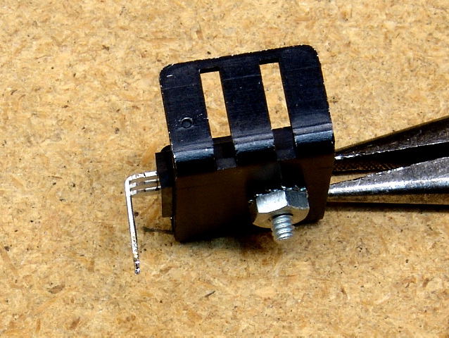 IC's - side view.
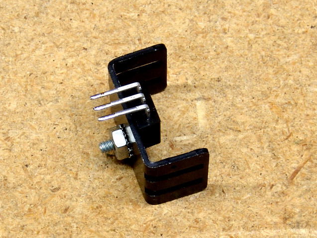 Assembled IC.
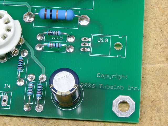 The U10 IC will be inserted here.
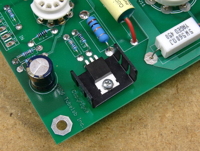 It is inserted as shown. The nut on the back of the heat sink spaces the heat sink above the board slightly to assist in air flow.
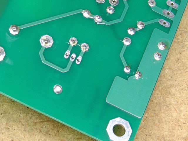 The leads protrude through the board, and the screw should come through enough to allow a nut to hold the assembly in place.
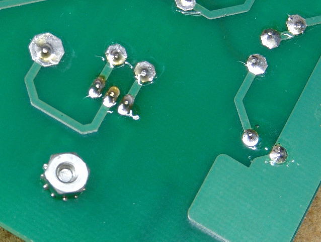 Place the lock nut on the screw and tighten it. Do not over tighten. This could cause the whole assembly to turn. It only has to be tight enough to keep it from falling off. Once the nut is tight, solder the leads.
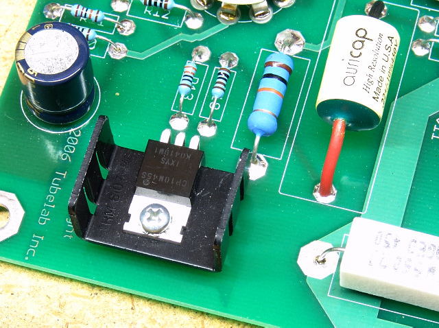 U10 done.
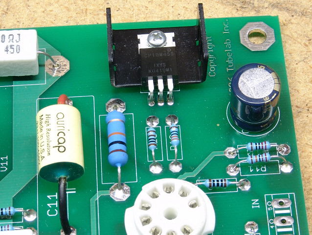 Another view.
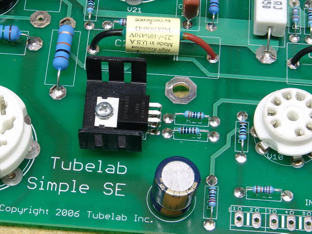 Repeat the procedure with U20.
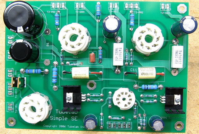 Your board should now look like this. If it does, proceed to the connectors page.
Installing the Semiconductors (inverted assembly)
In this method the semiconductors are mounted on the bottom side of the board. This allows slightly reduced air flow, but the semiconductors operate at a conservative temperature, so that this is not an issue. The reason for using this method is to allow the PC board to be mounted about 1/2 an inch below a mounting plate or chassis. This mounting method places the semiconductors below the PC board however other components have potentially lethal voltages on the exposed metal surfaces and leads. You MUST provide a barrier so they can not be touched by the user. This is usually the amplifiers top plate See the Enclosures page for details.
There is an alternate mounting method for the diodes that places them on the top side of the board laying down. This works with most mounting schemes, so please read it (bottom of the page) before starting, and use it if you feel it will work for you.
 We will start with the FRED diodes D1 and D2. They are the semiconductors with two leads. We will be installing them on the other side of the board. Installing a diode backwards will cause a very short unhappy life for the diode, C1, and possibly the power transformer! Since there is no screened legend on the back side of the board we must mark the board to ensure correct placement. Note the dot in the lower left hand corner of of the outline box for each diode.
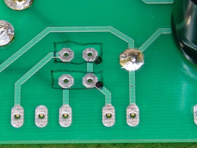 Draw the box for each diode on the back of the board. Put the dot in the same corner of the box that it is in on the other side of the board. The dots should be on top of each other. They should appear in the same spot if the board is held up to a bright light.
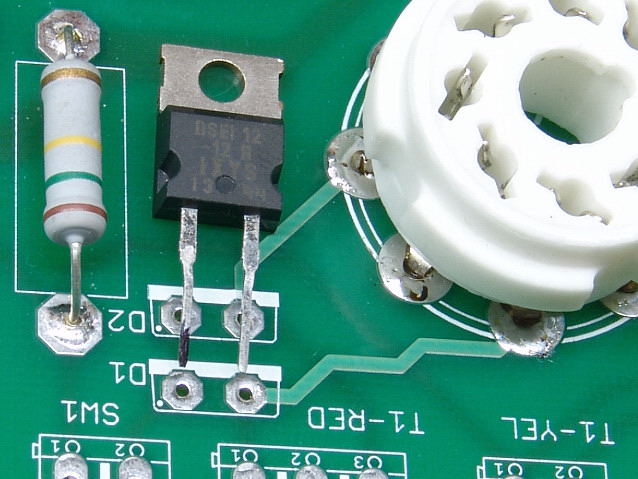 Place D2 on the top of the board as if you were installing it on the top of the board. Mark the tip of the lead that would go in the hole closest to the dot. This should be the left hand lead when the diode is viewed from the front.
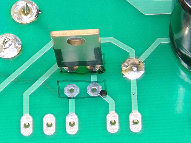 Insert the diode on the back side of the board so that the marked lead goes into the hole closest to the dot.
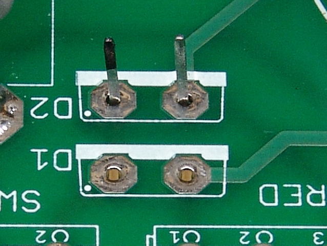 Verify that the marked lead is in the hole closest to the dot. Bend the leads slightly to keep the diode from falling out and solder the diode in place.
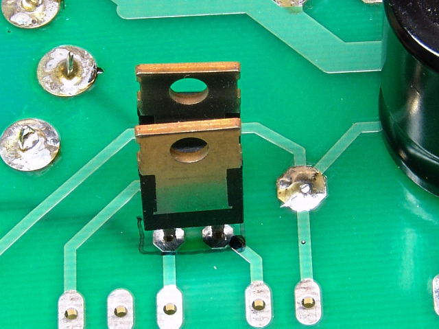 Repeat this procedure for diode D1. The diodes should look like this when done.
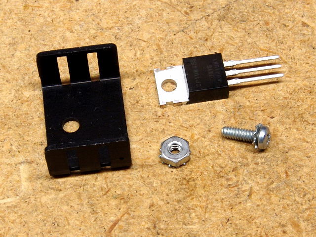 Next we will install the CCS IC's U10 and U20.
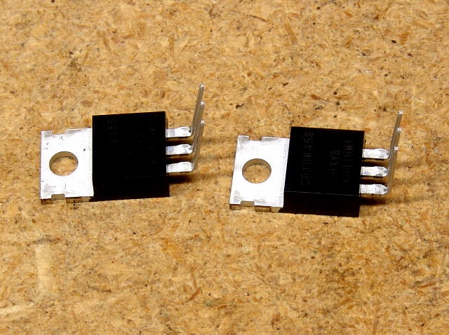 The leads must be bent upwards as shown. Note that these leads are bent in the opposite direction that they were when they were installed on the front of the board.
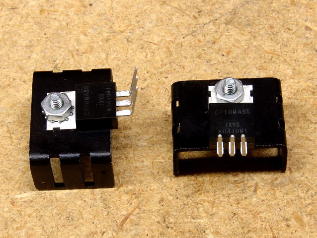 The IC's are mounted on the BACK SIDE of the heat sinks as shown. Tighten the screws.
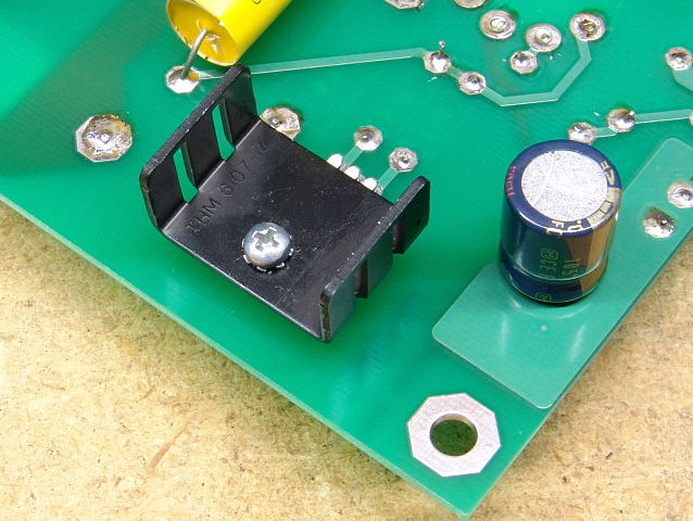 One assembly is inserted on the back side of the board at the U10 position.
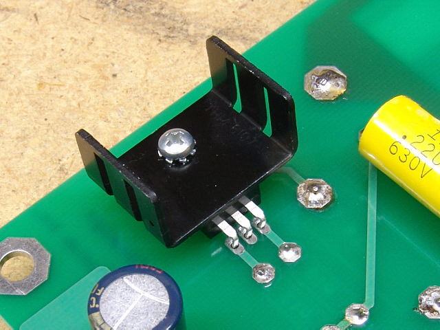 Another view.
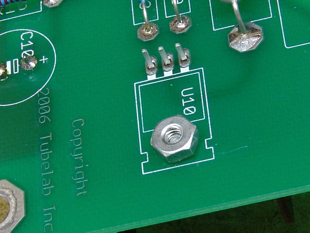 Place the lock nut on the screw and tighten the nut. Do not over tighten.
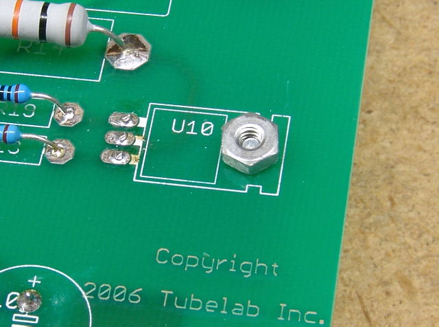 Solder the leads.
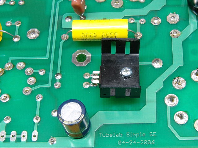 Repeat the procedure for U20.
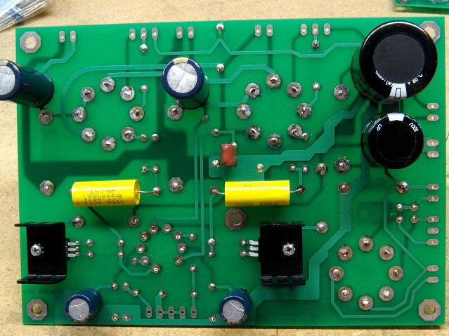 The semiconductors are done.
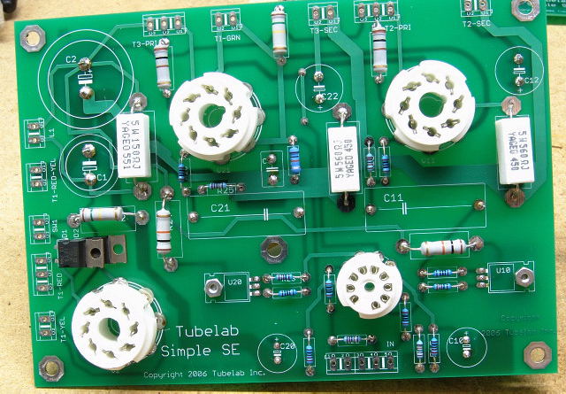 Top view.
Your board should now look like this. If it does, proceed to the Connectors page.
Alternate Method for Installing the Diodes.
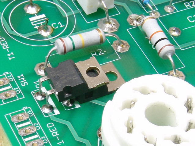
This is another method for installing D1 and D2. They are placed on the top side of the board, laying down. This makes accidental contact more unlikely, and works well with most board mounting schemes. Read this procedure, and substitute it for the assembly instructions for D1 and D2 in your semiconductor assembly procedures above if you think that it will work for you.
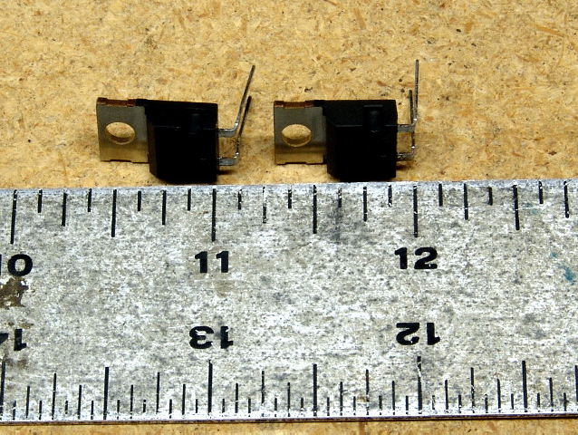 Bend the leads of both diodes as shown.
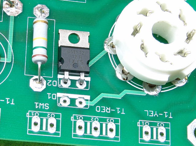 Insert one diode into the D2 position as shown.
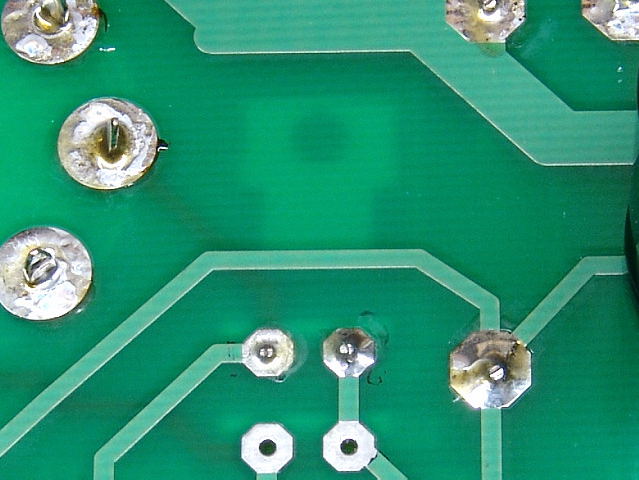 Solder it in place.
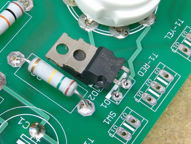 Insert the second diode in the D1 position on top of the D2 diode as shown. See the pictures below for more detail.
 Solder D1 in place.
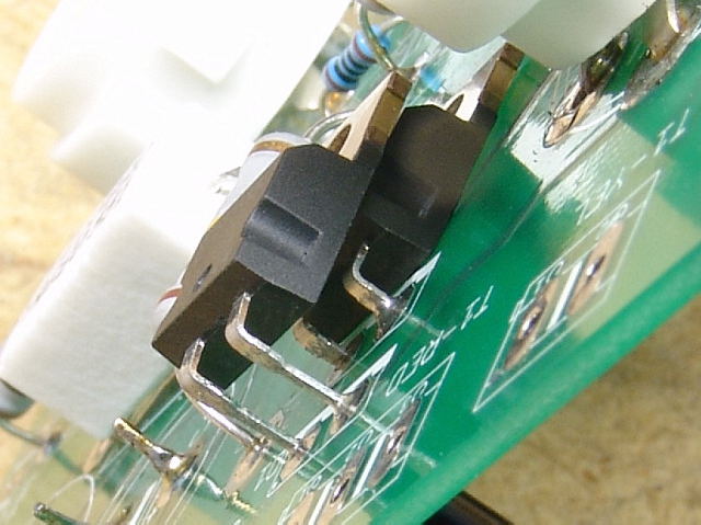
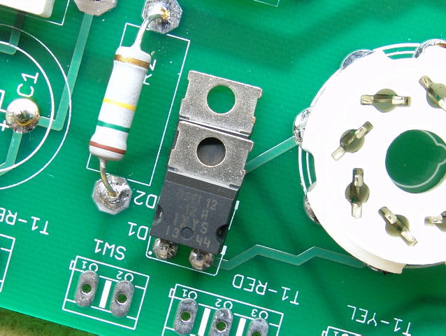 The completed diodes should look like this.