Table of Contents
- Getting Started
- Resistors
- Tube Sockets
Capacitors
- Semiconductors
- Connectors
- Wiring Diagrams
- Checkout
- Enclosures
Capacitors
There are two sets of assembly instructions on this page. The normal (top side assembly) instructions are first followed by the inverted (bottom side) assembly instructions. Your choice of enclosure for the PC board will dictate which method you use. Choose one method for assembling the board, and follow the same method for the remainder of the board assembly.
Your board should already have the tube sockets installed before installing the capacitors. Installing the tube sockets is difficult once the capacitors have been installed because the board can no longer be placed face down on a flat surface to ensure alignment.
Electrolytic capacitors have a polarity and MUST be installed in the correct direction.
There is a + sign on the board silk screen near the positive connection of each electrolytic cap. All electrolytic capacitors will be marked, unfortunately they are not always marked the same. On most current capacitors the NEGATIVE lead is marked with a stripe, which usually contains a minus sign. Most also have a longer lead for the POSITIVE terminal. Some will have marking for one or both terminals on the plastic adjacent to the terminal itself. Make absolutely sure that you identify the terminals on your capacitors before installing them.
If an electrolytic is installed backwards, it WILL fail. The failure is often instant and usually an explosion, often violent, which can cause serious injury. The chemicals contained inside these caps are caustic. They are not good for people, and will eventually eat the plating off of the PC board. This is the most common reason for many amplifiers not working on the first try.
As with the resistors, the capacitors are numbered by function. C1, C2, and C3 are part of the power supply. C10, C11,and C12 are part of the right channel amplifier circuit, while C20, C21, and C23 are part of the left channel amplifier circuit. There is no C4 through C9 and no C13 through C19 in this design.
Gather up all of the capacitors, the checklist, some tools, and lets do it.
Capacitor Installation (top side assembly)
I installed the capacitors in this board without the tube sockets in place. I did this in order to make it easier to photograph the capacitors illustrating the polarity. It turns out that I didn't need to do this (I didn't use those close up shots after all). It also proved my point about the order of assembly. It is impossible to lay the board down with the tube sockets on the work surface if there are already tall capacitors in the board. Your board should already have the sockets in place.
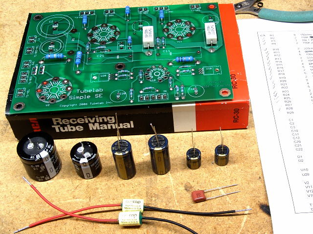
As with the resistors, it helps to identify all of the parts before starting assembly, and arrange them for easy identification. There are nine capacitors used on this board. Six of the capacitors are electrolytic which MUST be inserted with the correct orientation. These are the ones in the back row. Each one of these has a positive terminal and a negative terminal. Make absolutely sure that you can identify the terminals on these capacitors before starting assembly on this board. In this photo the negative terminal of all of the electrolytics are facing forward. The Panasonic (Matsushita, National) capacitors commonly used in audio amplifiers mark the NEGATIVE terminal with a stripe containing a minus sign. The leaded ones also have a longer lead on the POSITIVE terminal. Other manufacturers mark their capacitors in different manners, but they are marked.
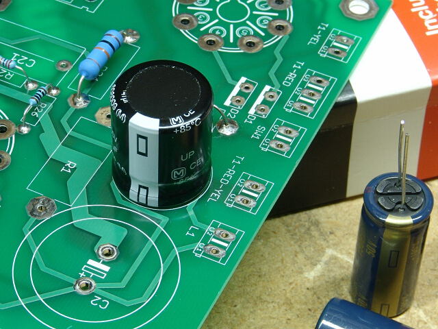 Insert C1 as shown. This is an electrolytic capacitor and has a polarity, meaning that it MUST be placed into the board with the correct orientation. It will physically fit either way. Make sure that you can identify the negative or positive terminal on your cap and install it with the positive side closest to V2 and the negative side closest to C2.
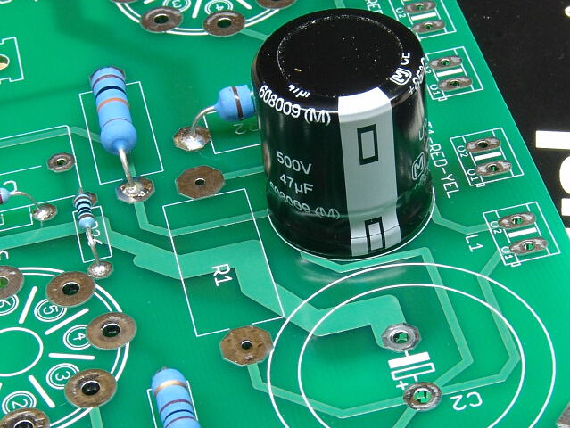 C1 handles the full output of the power transformer. If it is installed incorrectly, it could explode.
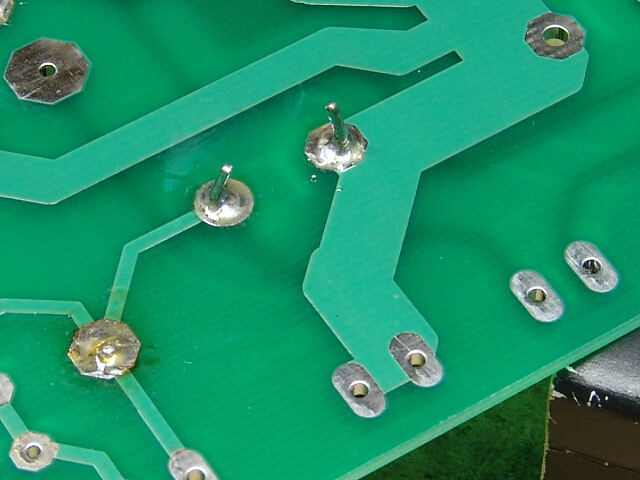 When you are sure that you have it oriented correctly, solder it in.
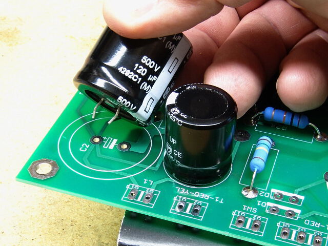 The same must be said about C2. The negative side goes next to C1, and the positive side goes toward the edge of the board.
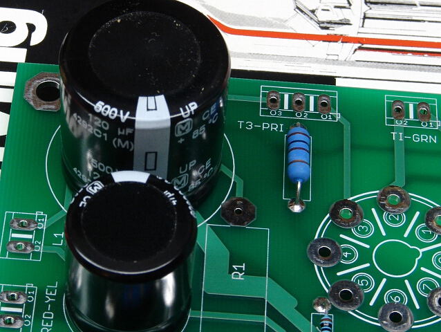 C1 and C2 look like this when installed. The stripe denotes the NEGATIVE lead on the Panasonic capacitors used here. They should be facing each other.
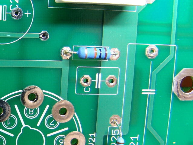 The silk screen lettering for C3 got messed up. The 3 fell through the hole. C3 is the small capacitor next to (and electrically in parallel with) R3.
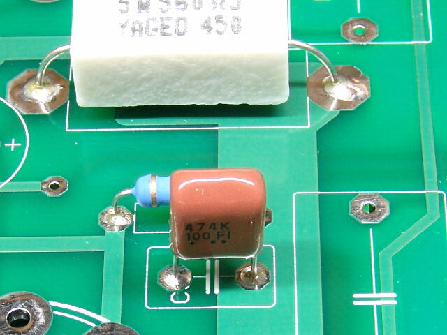 Insert and solder C3.
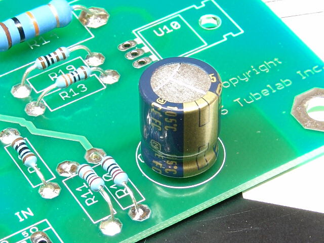 Next install C10. This is an electrolytic capacitor, which must be installed with the correct polarity. The negative lead is closest to the edge of the board.
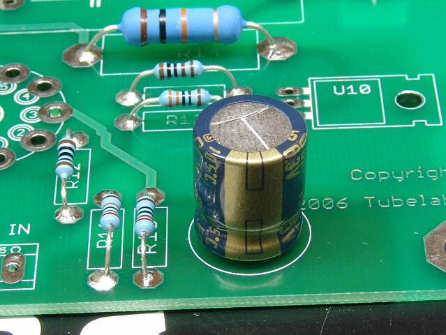 Another view of C10.
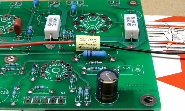 C11 is the right channel coupling cap. I have left enough room on the PC board to accommodate capacitors of many sizes. For a reasonable high end capacitor, I use AuriCaps. These things come with stranded wires that are long enough to reach the next country, so they must be trimmed.
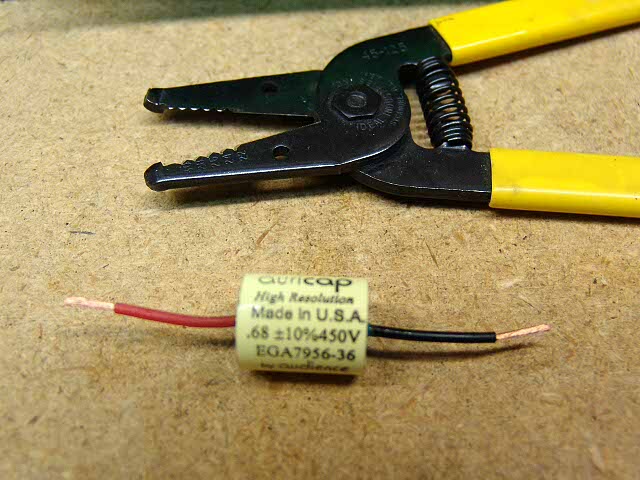 This is easiest with a pair of wire strippers like these. Cut and strip the leads to fit the holes in your board. It is important NOT to put any stress on the capacitor when doing this. Do not hold the capacitor while stripping the wire, hold the wire lead between the cap and the strippers. This photo is from a different design, hence the .68uF cap.
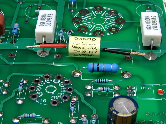 Here is the capacitor after the leads have been trimmed. I put a SMALL amount of solder on the leads. If you put too much, the leads will not fit in the holes. It may be easier to skip this, since the holes just fit the leads on an AuriCap.
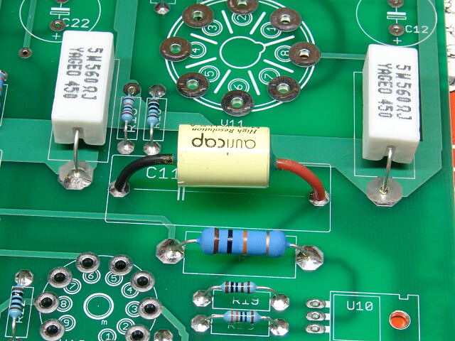 Here is the AuriCap installed. Technically these capacitors have no polarity, but Auricap colored the leads, so I put them in observing their color code. The red lead connects to R19 and the black lead connects to R15.
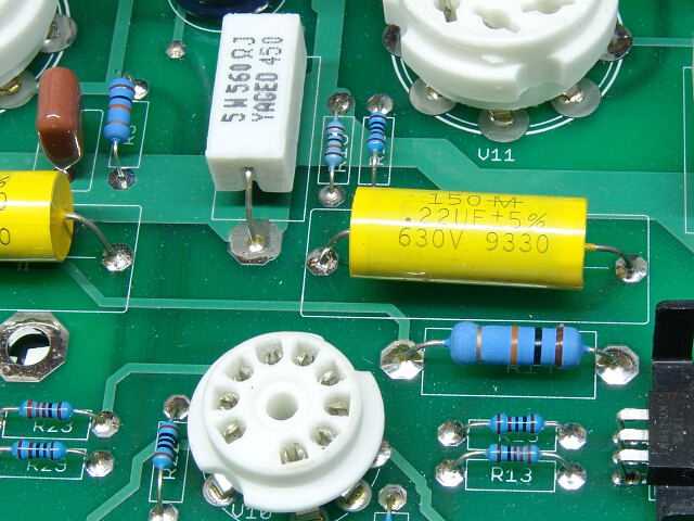 Here a standard (Mallory) capacitor is used for C11.
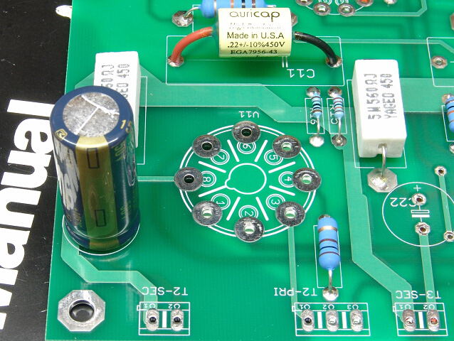 Insert and solder C12. Again this is an electrolytic, and polarity must be observed. The negative end goes toward the rear of the board. The positive end connects to R17.
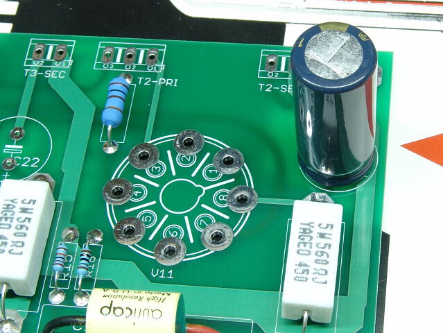 Front view of C12.
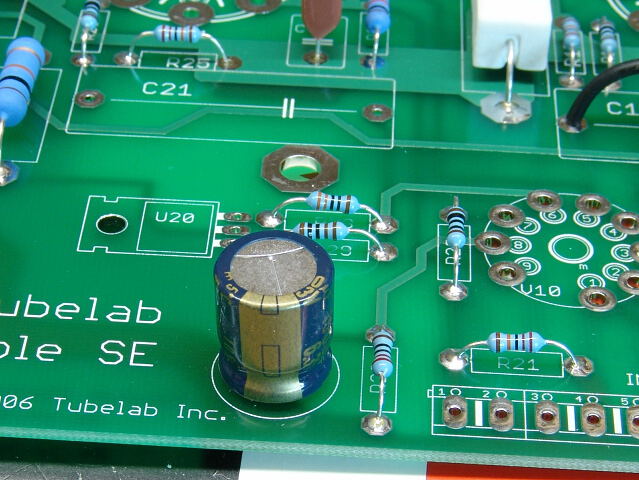 Next install C20. This is an electrolytic capacitor, which must be installed with the correct polarity. The negative lead is closest to the edge of the board..
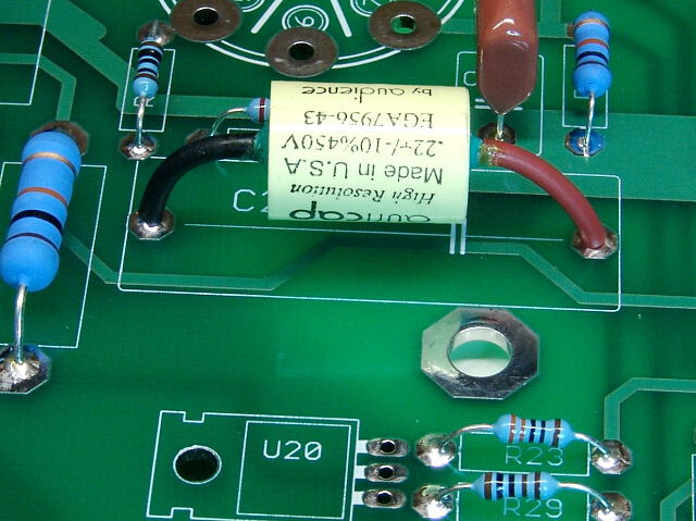 C21 is the left channel coupling cap. It is installed in a manner similar to C11.
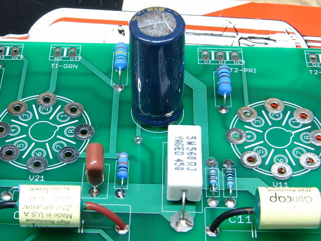 Insert and solder C22. Again this is an electrolytic, and polarity must be observed. The negative end goes toward the rear of the board. The positive end connects to R27.
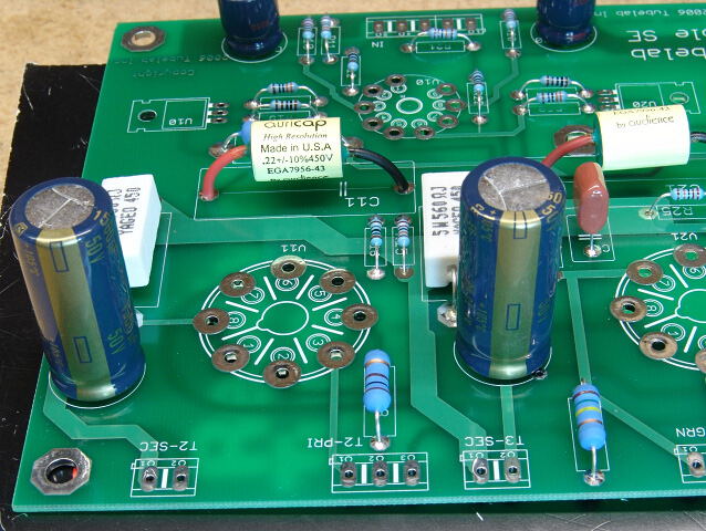 This is a view of C12 and C22 from the rear of the board.
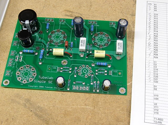 All of the caps should now be installed, and and of the capacitors should be checked off on your parts list.
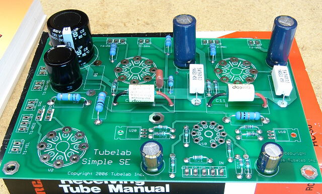 Front view of a board with all caps installed.
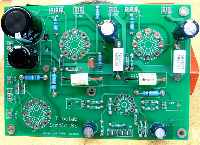 Overhead view of board with all caps installed.
There are a few more items that need installation on the PC board itself. If you are satisfied with your board so far proceed to the Semiconductors and Heat Sinks page.
Capacitor installation (inverted assembly)
Read the normal installation procedure above before starting because it contains information that may not be repeated here.

As with the resistors, it helps to identify all of the parts before starting assembly, and arrange them for easy identification. There are nine capacitors used on this board. Six of the capacitors are electrolytic which MUST be inserted with the correct orientation. These are the ones in the back row. Each one of these has a positive terminal and a negative terminal. Make absolutely sure that you can identify the terminals on these capacitors before starting assembly on this board. In this photo the negative terminal of all of the electrolytics are facing forward. The Panasonic (Matsushita, National) capacitors commonly used in audio amplifiers mark the NEGATIVE terminal with a stripe containing a minus sign. The leaded ones also have a longer lead on the POSITIVE terminal. Other manufacturers mark their capacitors in different manners, but they are marked.
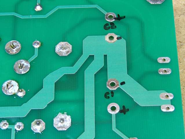
You are going to install the capacitors (and later other components) on the back side of the PC board. There is no silk screen on the back of the board. In order to avoid the possibility of installing a capacitor backwards, I mark the board with the reference designator (C1, C2, etc) and the polarity. If you are careful and use a fine tipped marker, you can put the marking on such that it will be covered up by the capacitor when it is installed.
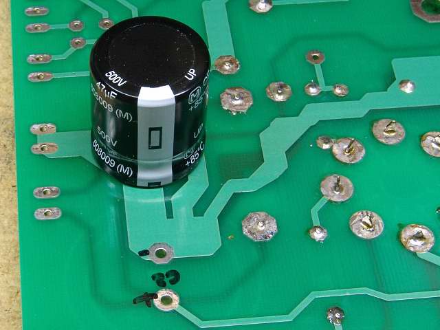 Insert C1 into the marked holes, paying attention to the polarity.
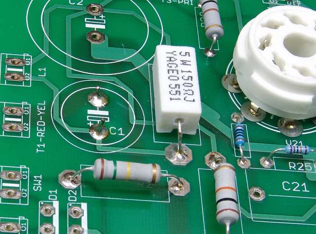 When You are ABSOLUTELY sure that C1 is in correctly, solder it in place.
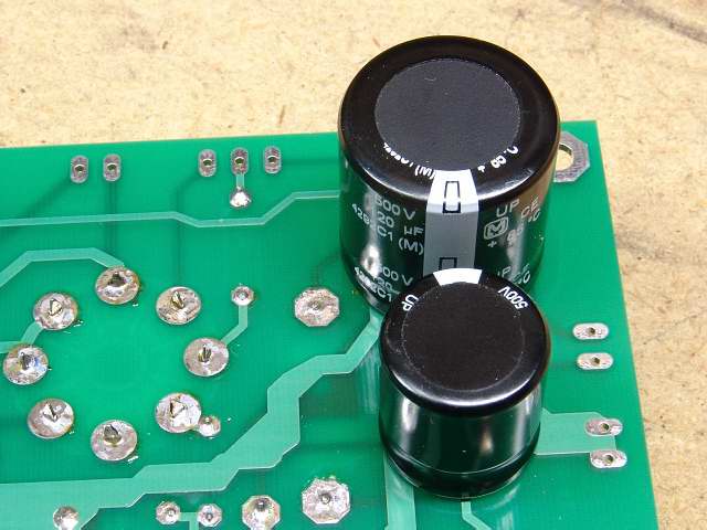 Insert C2 into the marked holes, paying attention to the polarity.
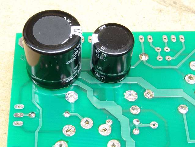 Another view of C1 and C2.
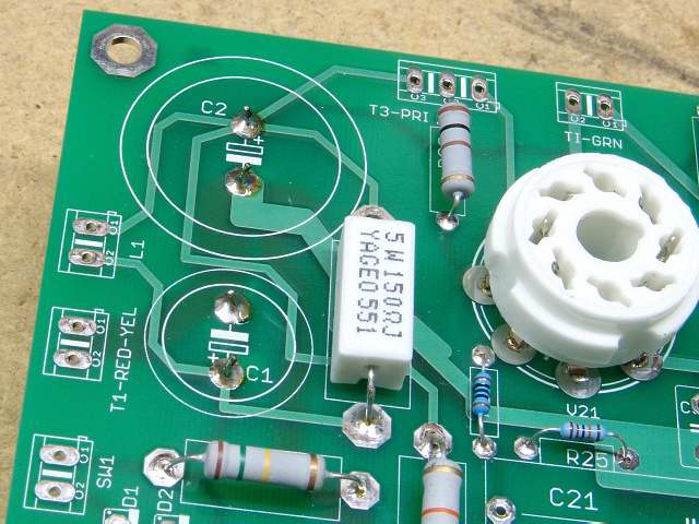 Solder C2 in place.
 The silk screen lettering for C3 got messed up. The 3 fell through the hole. C3 is the small capacitor next to (and electrically in parallel with) R3. It will be installed on the back side of the board.
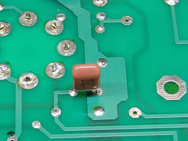 Insert and solder C3.
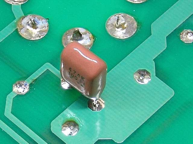 Another view of C3.
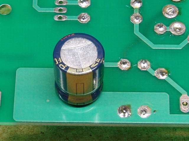 Following the procedure used for C1 and C2, insert C10.
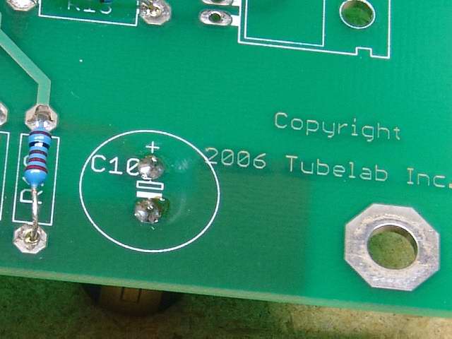 On many electrolytic capacitors the positive lead is longer than the negative lead. Verify that the longest lead is sticking out of the hole with the + sign next to it. Solder, and clip the leads of C10.
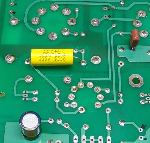 Install C11. Note the marked holes for the other electrolytic caps.
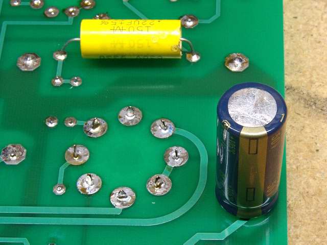 Install C12.
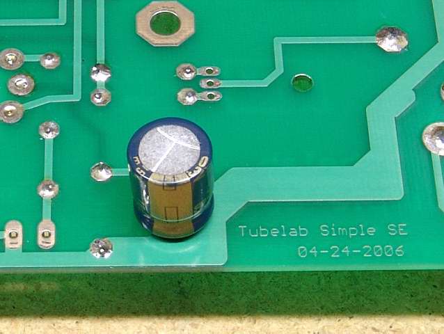 Install C20.
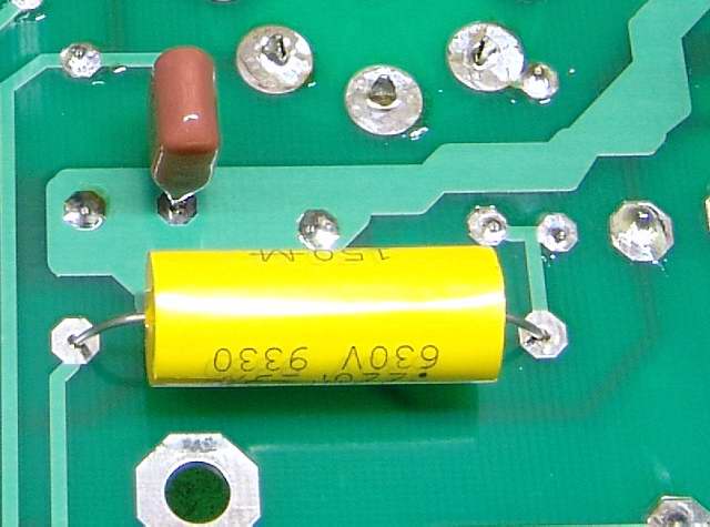 Install C21.
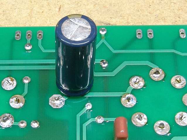 Install C22.
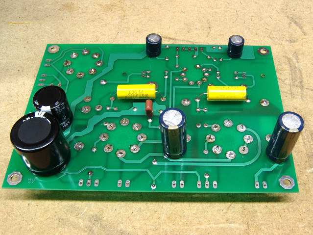
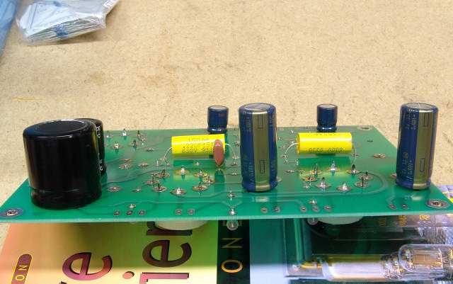
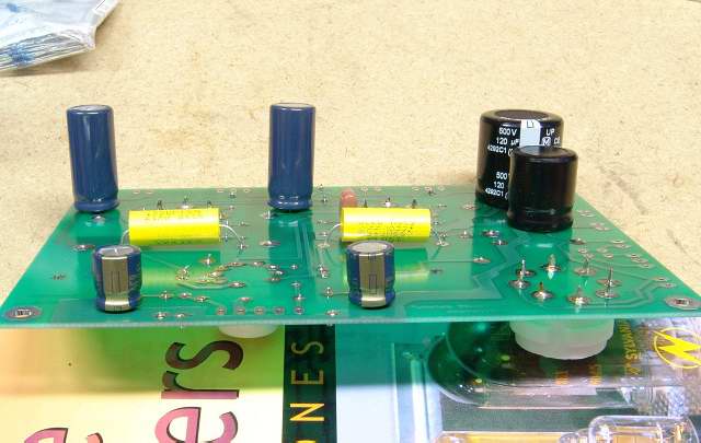
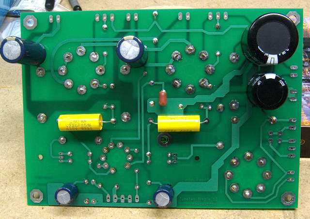
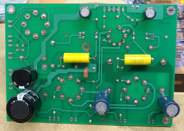 Verify that your board looks like the photos above.
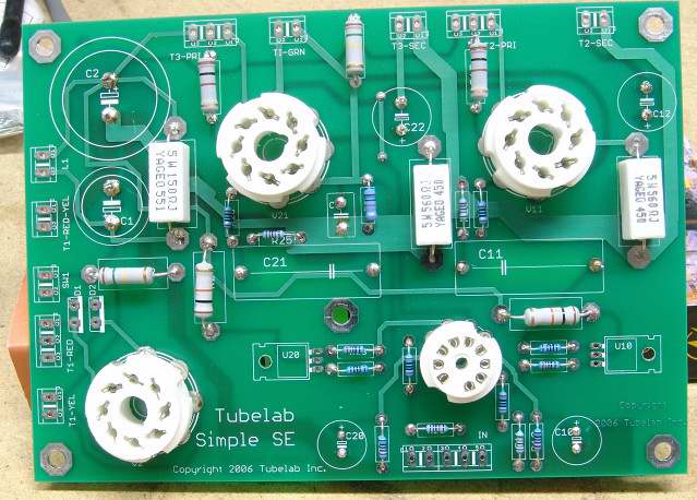 View of the top of the board after all of the caps were installed on the bottom.
There are a few more items that need installation on the PC board itself. If you are satisfied with your board so far proceed to the Semiconductors and Heat Sinks page.