This page describes the Tubelab SSE (simple single-ended) amplifier, and outlines its origins. Visit the links on the lower left to learn the detailed design methodology, and theory of operation. The PC boards are available now. Info is on the Tubelab SSE board page. Full construction details are in the assembly manual.
Notice!
The assembly instructions for the SSE show the optional installation of a standby switch. There have been a few instances of blown diodes associated with the use of a standby switch. Investigation has revealed that some power transformers (particularly Hammonds) can generate a 2500 volt spike when the standby switch is operated. It is recommended that the standby switch be omitted from new builds, and not used on existing amps. The instructions will be changed as soon as I can get to it.
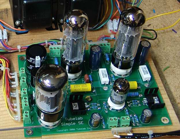 The new boards are available, they work great, and can be assembled easily. It took me 45 minutes to build this one.
Two things happened that led to the design of this amplifier. When the Tubelab SE amplifier design appeared on this web site, I started receiving e-mail. Many people asked for an amplifier that didn't use expensive tubes or unique parts. People wanted an amplifier that was easier to build. They wanted an PC board that could accommodate parts on either side so that conventional mounting could be used. People asked if it was possible to use connectors instead of soldering transformer wires directly to the PC board. They wanted an amplifier design that did not require bias (or any) adjustments. I listened to those requests.
At the same time several experiments were started because of my curious nature and a few suggestions on one of the diyAudio forums. One involved the testing of several sweep tubes for use in SE audio applications. Another involved the testing of a few different low cost SE output transformers. After a few of these tests I decided to connect the best low cost transformer (Edcor XSE15-8-5K) up to the best low cost sweep tube (6AV5) and drive them with a Tubelab SE board, power the whole thing with a bench supply, and apply a little cathode feedback to help out the smallish transformer. This turned out to be an exceptional combination.
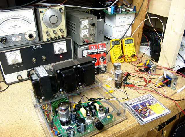 Here is a picture of that test setup
I then rewired the sockets to accept any of the popular audio tubes, and tested several types.
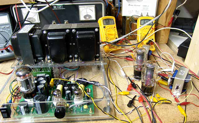 Here is a picture of that test setup with 6L6's
These experiments proved to be the beginnings of a great sounding, low cost amplifier. Some changes would be needed. Fixed bias and PowerDrive required a negative voltage source. The 5842 driver tube has become hard to find and expensive. The DC filament supplies of the Tubelab SE are not needed.
I got to thinking about the ultimate low cost SE amplifier. I even built a copy of one of the best selling low cost parafeed amplifier kits for reference (the one with a single 6DN7 per channel). I also have two Tubelab SE amplifiers for comparison. One is an unmodified 300B amp, and the other is set up like the picture above, with 6L6's. I need to design a low cost amp that outperforms the 6DN7 amp, works at least as good as the Tubelab SE with 6L6's, but costs less, and hopefully doesn't get shamed by my 300B amp.
The first major decision is the choice of output tubes. I really liked the sound of the 6AV5 sweep tubes, but they are not widely available, and their power handling capabilities varies wildly depending on manufacturer and vintage. The obvious choice is to use a common audio tube that is available world wide. The ideal choice would be to design an amplifier that could accept several different types of these tubes without modifications.
A few weeks of experiments and simulations led to a combination of components and operating conditions that will work well with a 6L6 or an EL-34 or a KT-88 without any changes. Other tubes of similar characteristics can also be used. The 5842 has been my driver tube of choice, but my supply is very low, and they have gotten far too expensive. After extensive experimentation, I settled on the 12AT7 - ECC81. This tube works almost as well as the 5842 and is available world wide for a reasonable cost.
Flexibility
With these decisions out of the way the rest was easy. Incorporate everything that people had asked for on the PC board. Tube rectifier or solid state rectifier? YES, switchable. Triode or ultralinear? YES, switchable, pentode mode is available if needed. Cathode feedback? YES, switchable. CLC power supply filter or CRC? Either, to be decided at build time, or switchable with an external resistor. Ability to add an external (off board) large power supply cap. YES, there are connectors for it on the board. I am currently using a large ASC motor run cap. All of the external connections to the board (transformers, switches, choke, inputs) are made through screw connectors. The PC board is designed so that the small parts could be installed on either side of the board. This allows conventional chassis, or metal plate mounting options.
The only unique part used is the IXYS 10M45S CCS IC. It increased the driver gain while reducing the distortion. I needed the gain, so I added it.
SE Power
What kind of power can I get out of it? With the recommended power transformer the tubes operate at 410 volts and can deliver 10 to 14 watts per channel in ultralinear mode and 5 to 8 watts in triode mode depending upon tube choice. More power is available in pentode mode. Distortion at 5 watts in UL mode is under 1% with any of these tubes. I am in the process of fully testing this amplifier with several different output tubes, in all 3 operating modes, with SS and tube rectifiers. The results will appear on the Specifications page.
Low Voltage Option
I have already received a few e-mails asking why I chose an operating point of 450 volts for a beginner level amplifier. This is a valid concern. I chose a 440 to 460 volt range because it affords the best possible performance for this simple design. I understand the need for an amplifier that operates from a lower voltage supply, and I am working on it. Initial simulations reveal that the same design will work at 350 volts with a lower power output. I will post the details on the low voltage version of this design as soon as it is thoroughly tested.
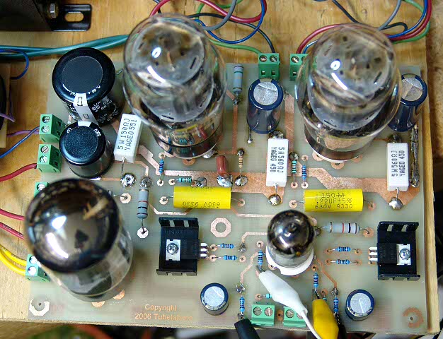 This is a picture of the prototype PC board.
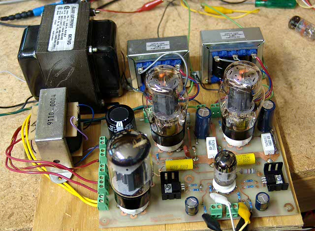 Here is a picture of the prototype amplifier.
Compatibility
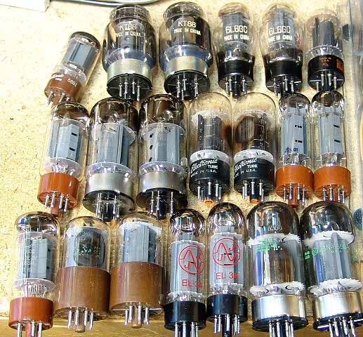
Yes, all of these tubes have been in the prototype amplifier. Yes, they all work well. No changes were made to the amp other than the tubes themselves. I have ran several more tubes through the amp since I took this picture. I have also tried about 6 different rectifier tubes 5U4, 5AR4, 5R4, and about 8 or 10 different types of 12AT7, ECC81, 6201 tubes.
Reliability
The prototype amplifier has been running almost non stop since It was built. If I am at home, it is ON. Often with no signal input. This causes the worst case dissipation in a Class A amplifier. Those who know me, and those who have followed this amplifier take shape across several threads on the diyAudio forums know that it is being thoroughly and severely tested far beyond anything a sane individual would subject it to. The B+ normally runs about 420 to 440 volts in this amp. I used a Variac to crank it up to 510 volts, and hammered it with loud rock for most of the past Saturday. The intent was to find out whose 6L6's and EL-34's could take it. I even played my guitar through it for a while. Nothing was damaged, but I did decide that I am not buying any more Svetlana EL-34's. The JJ EL-34's smiled throughout all of the abuse, as did a pair of Shuguang 6L6's that have already served a life sentence in a Bandmaster! I have some more tubes on order, so the abuse will continue.
When can I have one?
I have already heard this in an e-mail. I am rushing this along as fast as possible, but I won't make this available until I am SURE that it is ready.
The boards have already been sent out for commercial duplication. It takes about 30 days to get boards. I will build several amps in the process of shooting the pictures for the manual. These amplifiers will be severely tested to find any possible problems. This amplifier was designed from the start to be assembled by an inexperienced builder. The issues that appeared with attempting to create a kit from a design that was not meant to be a kit in the first place (Tubelab SE) will not occur. I would expect boards to be available around September, if I don't get any more unexpected surprises.
Will you offer kits or assembled amps?
That is certainly a possibility, but I can not say for certain at this time.
Does this amplifier live up to its expectations?
Absolutely! In the configuration that you see here, it will blow away those 1 to 2 watt SE amplifier kits. With some better output transformers, it can stand up to great amplifiers. Does it sound as good as the Tubelab SE? I don't think so. It is close, real close, but the sound of a true DHT is different. This amp with EL-34's in it comes close to matching the Tubelab SE in the detail department. It has better bass than the Tubelab SE with any tube, and way better bass with KT-88's. I intend to test this amp through the Electra-Print transformers that are on my Tubelab SE. Then I will have a fair comparison. I have already ordered some better transformers for testing. I will try them all when they all show up, and I have time.
Which threads on the diyAudio forums?
As I stated previously this amplifier evolved from discussions that took place on the diyAudio forums. They can be read for further info. I have listed the ones that I can remember here.
- Anyone know anything about a 6AV5GA
- TV Horz. Output Tubes used as Output Audio
- CCS, how it actually works
- Cheap SE output transformers
- The Edcor meets the 6AV5
- 6CD6GA in Enhanced Triode Mode for SE Amp
- Cathode and other types of feedback
- 6l6gc SET, my first DIY
- The Limitations of an EL34 in UL
Project Documentation