Table of Contents
Getting Started
- Resistors
- Tube Sockets
- Connectors
- Capacitors
- Semiconductors
Getting Started
The instructions on this page demonstrate the basic assembly techniques that I use to assemble boards. The photos were taken during assembly of several different boards. This information is useful for assembly of any PC boards.
This section will get you started assembling your circuit board. I have been assembling electronic devices both from kits and from scratch for over 40 years. I have designed one of a kind electronics devices, and electronic devices that have been put into mass production. In the production cases I have assisted in setting up the assembly lines, and tweaked the designs to improve manufacturability. I attempt to share some of these experiences here. If you are an experienced builder, please read this section and feel free to adopt any of these concepts that may help you. If you are relatively inexperienced, please follow these concepts, unless you have a better idea, or a unique circumstance. If this is your first electronic project, it would be wise to follow these concepts as closely as possible, and seek the assistance of an experienced person if you don't understand anything.
Component Choices
A few decisions must be made before assembly is started. This board was designed to make a stereo push pull HiFi amplifier. That is its intended use. Even when constrained to that application, there are a two choices to be made involving output tubes which affect some component values, and placement. Another possibility, the 30 to 50 watt mono block, will be added a bit later (if it passes my torture testing). The board is built according to the parts list and assembly instructions if EL34 / 6BQ5 (or similar) tubes will be used. The 6CW5 option requires substituting solid state diodes for the rectifier tube. If this option is chosen, do not install the octal socket for V-1. The capacitors specified for C1 and C2 will work in either case. Some builders may choose to use different capacitors when using 6CW5 tubes, although I have not found this necessary. R1 is a different value for each tube type. Make sure that you use the resistor that works with your choice of output tube. These are all outlined on the Tubes & Transformers page.
Some advanced builders will use this board for other applications, these would require a bit more thought involving what parts are placed on the board during the initial assembly. You need to make these decisions before starting assembly. Choose the components to be installed on the PC board during the initial assembly. Have all of those components, and only those components, available at your work space. I usually keep all of the components in a plastic tray, except for the group of parts being currently installed (caps, resistors, etc). I will lay these out on the bench for easy visibility.
Component Placement Options
Many builders will place the components on the top side of the board for ease of assembly. This makes the construction of a conventional looking amplifier (only tubes and transformers showing above a metal chassis or top plate) difficult without socket extensions. If you want to build an conventional looking amplifier, it is possible to place the capacitors, connectors, and some or all of the resistors on the back side of the PC board. This will allow mounting the PC board below the chassis with just the tube sockets protruding through the top surface. This decision must be made before assembly is started. If this path is chosen, the tube sockets are installed in the normal manner, and you will use the inverted assembly instructions for the remaining components. Two sets of assembly instructions are provided on the resistors, capacitors, tube sockets, and connectors, pages for this purpose. Be sure that you follow the same technique throughout your assembly.
It is important to take your time and don't try to rush the assembly. It takes me about one hour to populate (put all of the parts on, and solder) a board, with all of the parts laid out in advance. I have built about 10 of these boards, and I know where all of the parts go. Others who have built this board took from 2 to 5 hours to assemble it.
This board is slightly larger than our other boards. It contains more parts than our Simple SE, resulting in a higher component density, but is still relatively easy to assemble. No modifications are required on any of the parts, just insert them as shown and solder. Pay particular attention to the parts that MUST be inserted in the correct orientation, and your board will work on the first try. There are no jumpers required on this board, so there is no Final Assembly page.
Order of Assembly
This components should be inserted in the correct order to assure that it is possible to fit all of the components in the board. It is important that the resistors be installed first. You may not be able to easily insert them after the large parts have been inserted.
The pictures shown in the assembly manual were shot during the construction of FIVE different boards. They were not all assembled in this order so some pictures may have different components shown in the background. I built them in different orders to find out what works best.
It is advised that you follow this order:
The tube sockets need to be installed before the capacitors when inverted assembly is used. This will ensure that there is ample space to solder the tube sockets since they must be soldered on the back side of the board. It is easy to melt a capacitor if they are installed first. Yes, I burnt one! It still worked, but you may not be so lucky. Some of the connectors get placed in between tall electrolytic capacitors. They can be difficult to keep pressed against the PC board after the tall capacitors are installed.
After your board has been populated, set it down, and take a break. Come back later with fresh eyes and go over your work. I have found errors in my own work this way. Don't skip this step. Look for poor solder connections, solder bridges, wrong parts installed in the right holes or the right parts installed in the wrong holes. I would check the installation of each electrolytic capacitor to make sure that they are facing in the right direction.
The component density is higher on this board than it is on the Simple SE. Some components are close together so the probability of solder bridges is higher on this board. Look at the board again in these areas making sure that no solder is bridging between the two connections. Check both sides of the board:
- R105 and R108
- R101 and V100 pin 8
- R103 and R104
- R203 and R204
- C205 and V202 pin 1
- C203 and V201 pin 1
Note, solder bridges may form between two components that are adjacent and connected together. This is normal (and does not need to be fixed) on the following component pairs:
- R110 and R111
- R114 and R115
- R115 and V102 pin 2
- R210 and R211
After you are convinced that all is well, put the board aside, and begin assembling your amplifier. After the amplifier is assembled proceed to the checkout and setup page.
Tools
You will need some tools to assemble your board. You will obviously need a soldering iron and some solder. Make absolutely sure that your solder is rosin core or flux core solder made for electronics use. Acid core solder will destroy the parts and the board. Acid core solder is the type typically used by plumbers to solder pipes.
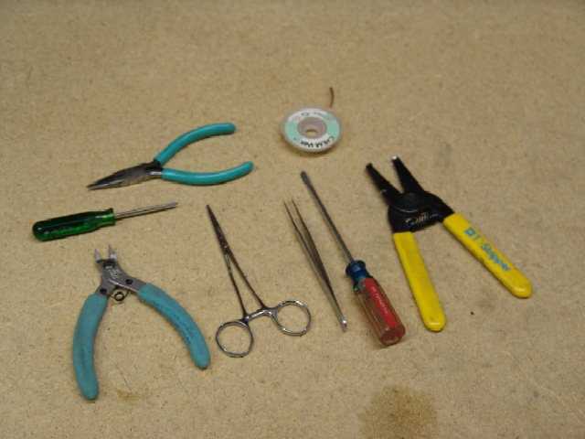
You will also need a set of wire cutters (also called diagonal cutters or dikes). A pair of needle nosed pliers are also needed. The following other tools may be useful, wire strippers, tweezers, screwdrivers, hemostats (also called seizers) and some desoldering braid (Solder Wick). It is likely that these tools will be needed later in the final assembly and checkout. These are covered below. You will also need one or more digital voltmeters (also called a multimeter) to check out and adjust the amplifier. The preferred checkout procedure for this board uses three meters. This will be covered later.
The Soldering Iron
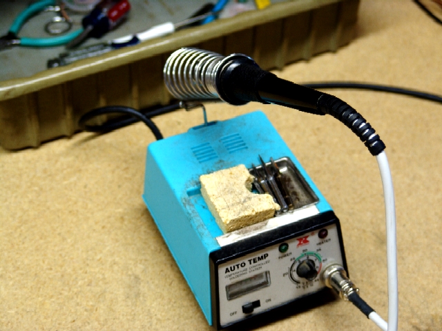
In order to solder parts onto the board you are going to need a soldering iron. It doesn't need to be a fancy microprocessor controlled digital wonder iron, although there is nothing wrong with that. At work I use a Metcal digital wonder iron, and it does practically solder by itself, but it costs over $1000. For the rest of us who have to buy our own equipment, an adjustable temperature iron is nice but not mandatory. You need an iron with a heating element between 40 and 100 watts, capable of holding the tip temperature around 600F or 325C. If you have to purchase an iron, I would suggest an adjustable temperature model, similar to the one shown below.
I have used this one for over 10 years and it still works great. I got it from Jameco, it is a Xytronic model 168-3CK. It is still shown on their web site at $89.95. They also list a 40 watt Weller for $48.95 and a 45 watt Xytronic for $59.95, but I have not used either one of them. It would be wise to purchase some spare tips in different sizes.
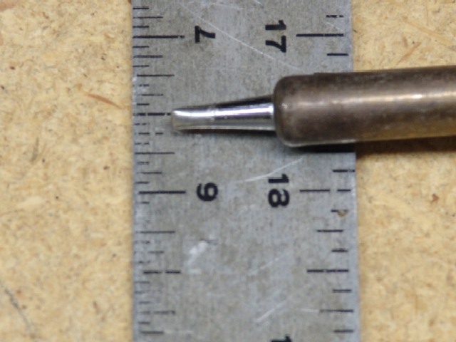
Your iron should have replaceable tips. For this board the best tip will have a 1/8" point. The typical pencil point used on modern surface mount boards is too small to heat up the large pads used on this board.
Make sure that the irons cord does not hang too far over the edge of the bench. If it gets caught on the arm of your chair, the iron could be pulled out of its holder when you move your chair. Trust me, it is really NO FUN to drop a hot soldering iron in your lap.
The Small Tools
These are some of the tools you will need to work with electronic devices. These can be purchased at Radio Shack, Harbor Freight, Jameco.com, JDR.com and other stores.
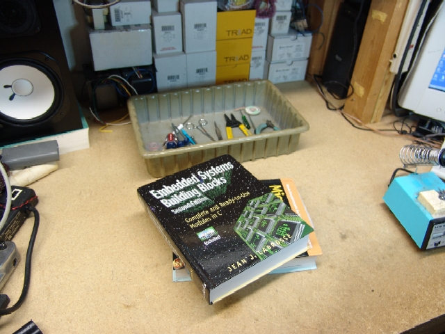
I like to keep them in a small plastic tray to keep the work area neat. This is helpful during the testing phase of the project where loose conductive items could be dangerous.
Your Work Space
Populating your board (soldering the components onto it) is easiest if you have sufficient unobstructed work space to set up the tools, soldering iron, the parts, and the board. Since this board has an extensive set of instructions that are computer based, it helps to have a computer nearby. I will spread out the parts that I am going to use next such that they can be easily seen and identified.
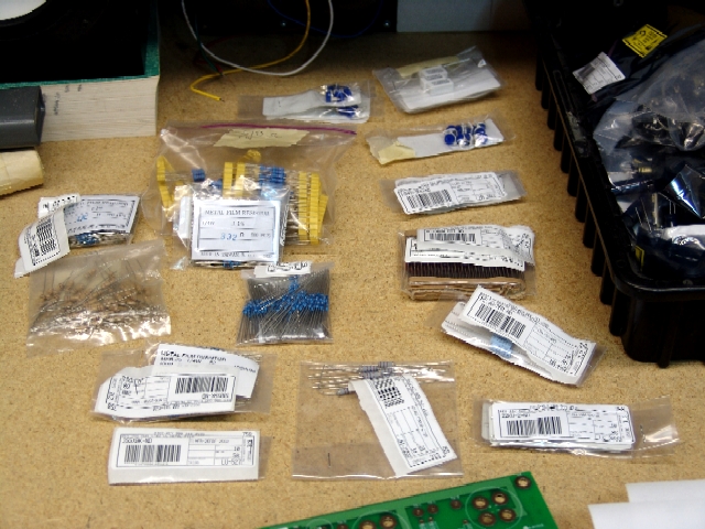
In this photo I have placed all of the resistors in a manner that they can be easily identified. I keep all of the other parts in another tray so they will not get lost. If you have been collecting other electrical parts, keep them separated from the ones used for the board to avoid any confusion. The parts not being used immediately are in the tray to the right.
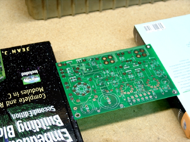
Some means of supporting the board is needed to allow for easy soldering. There are several gadgets out there designed for this purpose, but I prefer the low tech approach, two large books that are the same size. They must be thicker than the tallest part on the board.
The books are set on the work surface, spaced slightly less than the board is wide. The board can be set on top of them such the components can hang freely between the books. This way the parts can be inserted in the board, and the board flipped over. The parts can be soldered and then allowed to cool without being disturbed. The technique will be explained further in the next section.
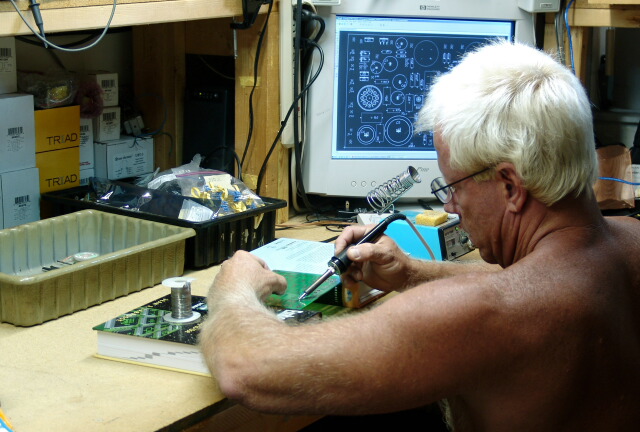
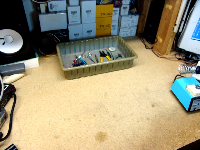
My work area is shown here. Not quite visible in this photo is the shelf above the transformers. All of the test equipment is on this shelf, and the shelf above it. The scope probe is visible in the upper left. This keeps the equipment out of the way until needed. The PC visible in the photo is also used for amp testing via the high end sound card and specialized software. I have the board overlay on the PC screen since the silkscreen on the actual PC board can be hard to read in some places. I also have a checklist on paper to keep track of each part as it is installed.
Working With the PC Board
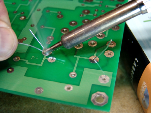
Working with a PC board requires some soldering techniques somewhat different than point to point wiring. First, your soldering iron should be set at 600 to 650 degrees F. If it is too cold, the soldering time will be too long, and the solder may not be evenly melted. If it is too hot, the board could be burnt or delaminated.
To insert a component gently bend its leads at right angles to the body of the part. The bends should be smooth, bent by hand. I don't recommend it, but you can bend the leads with needle nosed pliers. if you do this, the leads must be formed in such a way that there is no physical stress on the part once it is installed in the board. The part must have enough slack in the leads so that no stress is applied to the part as it (and the board) expands as it gets hot.
The leads should then be inserted into the appropriate holes in the board. The part is pushed down toward the board, but not flush to it. There should be a space between the part and the board. For most parts the spacing should be about 1/8 inch. There are two reasons for this. Many parts generate heat. The space allows for air all around the part, assisting in heat transfer. Tube amplifiers get hot, this heat causes thermal expansion. Parts drawn tightly to the board don't have room to move as they expand. This turned out to be the reason for failure of many components on the circuit boards in the first generation PC board products, especially early TV sets ( I worked in a TV repair shop in the 60's).
After the part is inserted into the PC board, the leads should be slightly bent outward to prevent the part from falling out when the board is flipped over for soldering. Do not bend the leads more than needed to keep it from falling out. Doing this will make it difficult to remove the part if it becomes necessary.
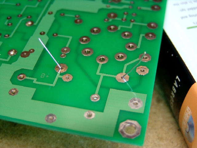
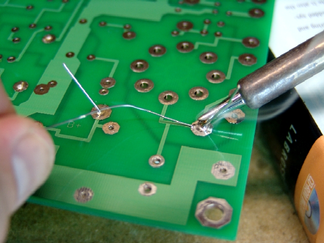
Each lead of the component is then soldered in place. The pads on this board are oversize where possible to aid in soldering.
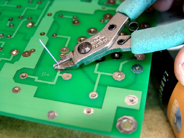
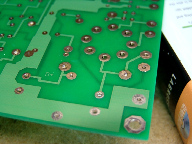
When soldered correctly enough solder should flow through the board to the top side to cover the pads on the top. Too much solder will pile up and flow down the lead to the part. Not enough solder is far better than too much. The board has plated through holes. Solder on the front side of the board is not necessary. It does help physically stabilize the part. If the part is soldered OK on the back, and no solder flows through to the front, the solder joint is probably OK.
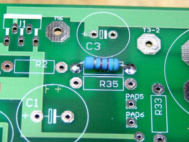
If you look carefully at the parts shown here you can see that there is actually see that there is more solder on the front side than on the back. This is an indication that enough heat was applied to the joint, and that gravity did its job. If there was not enough heat applied there may be far more solder on the back side since heat (and melted solder) never made it through to the front side. I would not recommend trying to solder the front side of the board. If the back of the board looks OK, leave the joint alone. If the back of the board does not look shiny reheat the joint and apply a little more solder. The reason that I am explaining this is for you to get practice on the resistors (which are not terribly critical) before attempting the tube sockets and semiconductors, which are far more difficult.
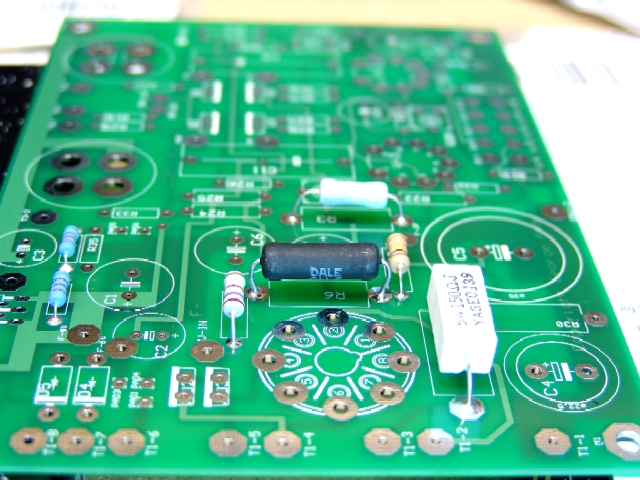
This is what your board should look like after a few resistors have been installed. This is a Tubelab SE board. Other boards may have different parts in different places, but I am showing several different sized resistors here so that you can see the details.
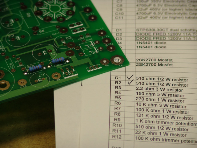
There are two parts lists included on the CD. The parts purchase list shows each unique part and the quantity of each that are required per board. Also listed are suppliers for each part. The assembly parts list itemizes each part in alphabetical order, there is a check box next to each part. It is recommended that this list be printed on paper. Check off each part as it is installed. This makes it far easier to keep track of your progress. It is especially valuable if you can't finish the whole board in a single session.
The resistors are the first components to be installed on the board. When you are ready to begin assembling your board print out the Assembly Parts List and proceed to the Resistors page.
