Assembly Manual • Schematic • Parts List • Tubes and Applications • Theory of Operation
The Amplifier Design
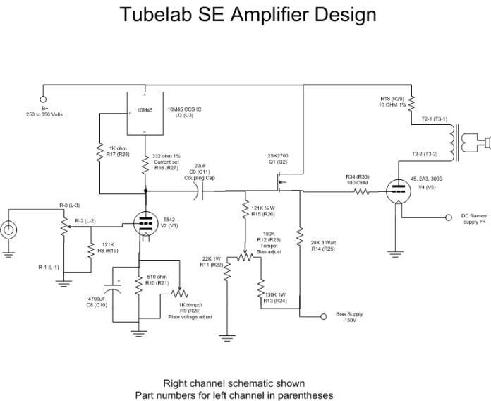
Here is the schematic for the amplifier portion of the Tubelab SE. You will see that it is similar to the third version of the Simple 45. There are only two improvements since then. A potentiometer is added across the cathode resistor of the 5842. This is used to compensate for tube variations. This allows the bias on the 5842 to be adjusted to put the tube in the most linear portion of its curves. The major improvement is the addition of the MOSFET at the grid of the output tube. This turns out to solve a lot of problems that have been present in vacuum tube amplifiers forever. For a detailed explanation of this issue, see the PowerDrive page. Some component values have been tweaked since the original design. These come from building and listening to seven of these amplifiers with a variety of different output tubes and transformers.

The circuit looks complex, but it can be broken down into small pieces.
Input Stage
The input stage (5842) is a simple common cathode amplifier. If you ignore the three parts (the 10M45 chip, 332 ohm and 1K resistors) where the plate load resistor belongs, it looks like any other common cathode amplifier. These 3 parts create a CCS (constant current source). A CCS passes a constant amount of current regardless of the applied voltage. In this case it is 12mA, set by the 332 ohm resistor. A constant current is the ideal load for a triode. By using a CCS the stage gain goes way up and distortion goes way down. I have tried various vacuum tube and solid state CCS circuits. Very few work as good as this, and they are much more complicated.
MOSFET Follower
In many amplifiers the coupling capacitor is simply connected to the grid of the output tube, and a high value (100K up) resistor goes from the grid to the bias network. The evils of this arrangement were documented by Norman Crowhurst over 50 years ago, yet this continues to be a popular design. Just look up the schematic of your favorite 6SN7-300B amp. Several engineers have tried to overcome this problem with novel circuits. The two most common are the interstage transformer and the cathode follower. I have experimented with these circuits, but have found that a MOSFET follower simply works better. The purpose of any of these circuits is to present a high impedance load on the driver and a low impedance source to the grid of the output tube. I called the combination of the CCS and the MOSFET, PowerDrive, for lack of a better name, and in reference to its function. More details are on the PowerDrive page.
Output Stage
The output stage is conventional with two exceptions. The grid resistor is much lower than normal. PowerDrive allows this, and the output tube likes the lower resistance. The other exception is the use of DC on the filament. Most "experts" state that DHT's sound better with AC on the filaments. In my testing I found a vague haziness in the sound. I could not hear any hum, but something wasn't right. When I got the FFT analyzer it became obvious. Even though I could null the 60Hz hum out with the balance pot, I was getting intermodulation products from the 60Hz. In other words when you ran a 1000Hz tone through the amp, you got 1000Hz, and 1060Hz and 940Hz out of it. These intermodulation products were not strong, but caused an annoying fogginess to some music. I substituted a DC power supply for the filament transformer and all of this just went away. The final design uses DC for all of the filaments. This has been tried with dozens of tubes of several types, mostly 45's, 2A3's and 300B's.
The Power Supply Design
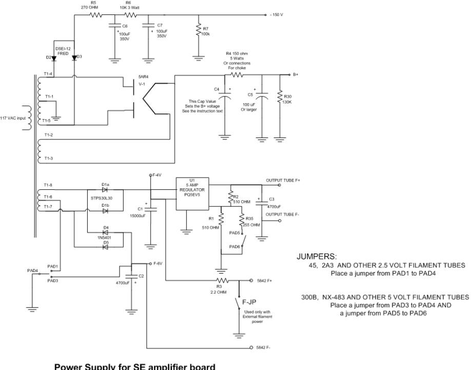
The on board power supply uses FRED diodes for the bias (negative) voltages. This allows fast startup of the bias supply. The plate (positive) voltages are tube rectified. A 5AR4 is recommended because of it's slow warm up characteristics. This allows all of the amplifier tubes time to warm up before the plate voltage is applied. The plate supply can be choke or capacitor input. There is room for a large power supply cap if you want one (to the left of the volume control), although it doesn't seem to make much difference. Provisions are made for an external bypass capacitor from the B+ side of the output transformer to the output tube filament (ground). An oil cap, a Solen Fast Cap, or a motor run cap may improve the sound. All filaments run on DC, there is no audible hum. There is a voltage regulator to assure that the DHT's receive the correct filament voltage with very low ripple. If it seems that considerable time was spent on the power supply, you are right. The power supply is an integral part of the signal path in an SE amp.

I have switched to a 5 terminal filament regulator made by Sharp. It has a lower dropout voltage. This is needed when using 2A3's with the wimpy Allied transformer and low line voltage. I don't recommend that combination since the Allied transformer is only rated for 3 amps and the 2A3's draw 5, but I sometimes run my Lexan amp with 2A3's and it has the Allied transformer. I have not had any problems yet.
The filament voltage can be set to any voltage from 2 to 5 by changing a resistor value. Jumpers are provided for dual voltage (2.5 or 5 volt) operation.