I did several experiments about 5 or 6 years ago, concerning totem pole configured push pull output stages and SRPP output stages. I unfortunately did not document them well. I tried several of the popular audio tubes and a few others. I remember that the EL34 was the best tube that I tried and that 6AS7's were the worst due to bias drift. The DC point would shift enough over time to cause distortion or total runaway.
I eventually set aside the totem pole design, but I tried a few experiments before disassembling the prototype. I had tried using two dissimilar tubes including a pentode for the top tube and a triode (or triode wired pentode) for the bottom tube. This led to configuring the top tube as a CCS. The amp did not have a lot of power, and was grossly inefficient, but worked extremely well.
Recently I decided to re - visit the Totem Pole and CCS loaded output topologies since Triode Electronics came out with a driver transformer with 4 independent secondaries. I want to build an H bridge output stage using tubes. I actually had one almost completed, but a hurricane last year postponed all Tubelab experimentation back for about 3 months.
During the 3 months that the lab became a storage shed (because my storage shed blew apart during hurricane Wilma) a thread was started and progressed on the diyAudio forums.
It talked about using a CCS load in place of the choke in a parafeed SE output stage. I had breifly experimented with this before, so I participated in the discussion.
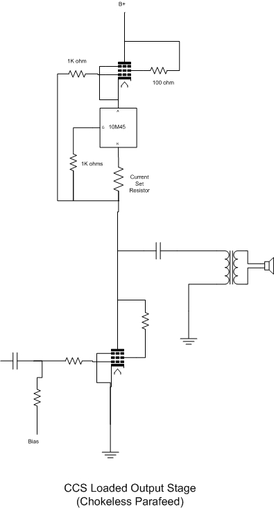
It has been stated that the ideal load for a triode is a constant current source. It would seem that a big CCS could be used as the load for a triode output stage. The choke in a parafeed circuit performs this function. A CCS circuit can work quite well in "chokeless parafeed" applications. It should be noted that A CCS does not have any inductance, and therefore can not provide the ability for the plate voltage to swing above the supply voltage. To make up for this the power supply voltage must be increased to allow for the signal swing above the original supply voltage. This means that the efficiency for an amplifier of this type will be very low. To help with the low efficiency a CCS that has a low saturation voltage is required.
This usually means a solid state CCS. I had already been using the IXYS 10M45 CCS IC in some of my designs. I (and others) have stated that the IXYS chip works great, but it does have limitations. It handles 450 volts max, and 35 watts max. It also doesn't seem to work well at very low currents. I have applications that require more voltage and more power. IXYS has a new chip that claims 900 volt capabilities, but you can't get them anywhere. I wanted to try a hybrid approach with an IXYS chip in the cathode circuit of a pentode to attempt a 100 watt capable CCS. I put one together with clip leads on a corner of the bench and tried several different tubes in it. Those experiments are on the CCS Circuits page.
After I had a working hybrid CCS, I just had to build something with it. I had been reading about other peoples experiments, and I was inching to do some of my own.


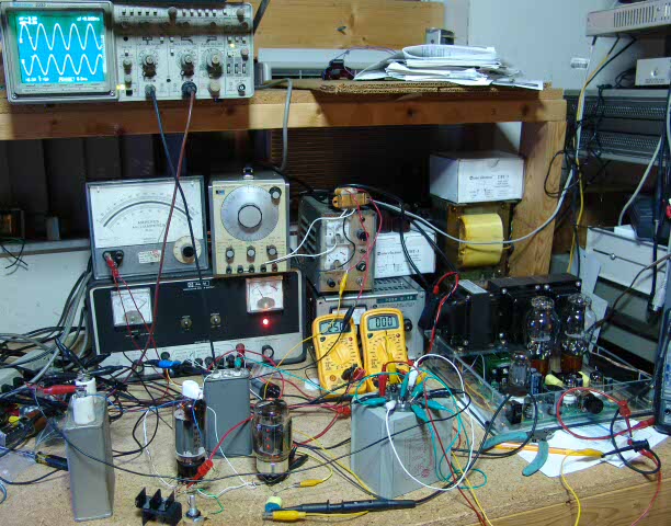
My work room was still a mess, but I cleaned off a spot, and "built" a basic amp. It is an unsafe mess, so as they say on TV, "Don't try this at home."

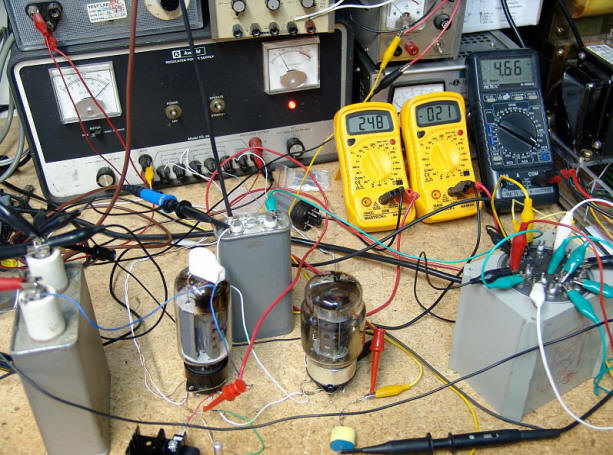
This is a prototype output stage using a 6LW6 CCS and a KT-88 SE output stage. The tube on the left is a 6LW6, The IXYS chip is mounted on the small heat sink at the front of the picture. Together they form a CCS that goes from 10 to 100mA, adjustable, and can handle up to 990 volts. The tube on the right is a KT-88 connected as a triode. It uses fixed bias, from the power supply in the background. The capacitor between the tubes is the parafeed cap, and a UTC output transformer is on the right.
The meters show 248 volts across the KT-88, -21 volts on its grid. The grey meter shows AC output voltage across an 8ohm load. This works out to 2.7 watts. The analog meter on top of the power supply (upper photo) shows a tube current of about 75mA. The scope shows the input and output signals.
The power output of this circuit is limited by the available voltage swing. With a 400 volt supply, I found that the most power was obtained at a plate voltage of 250 volts. If I had a 700 or 800 volt power supply this circuit would ROCK.
Since this circuit has no DC flowing through the output transformer, it is possible to use a resistor for the load to test the performance of the circuit without the transformer. I tried resistors of varying size to find the optimum load for this amp. It produces just over 3 watts with a 2600 ohm load. The distortion rises pretty rapidly below 2500 ohms, and the power begins to drop above 3000 ohms.
Now, the inquisitive mind will ask, what is the frequency response of this power amp without the limitations imposed by the output transformer? Well, now it is easy to measure. The low end extends to 18 Hz. This is limited by the parafeed capacitor size. The high frequency response extends out to over 800KHz. Yes, I could put an antenna on it and broadcast on the AM radio band!