I have performed bench testing on amplifiers (both tube and solid state) ever since I worked in the stereo shop 35 years ago. The setup has been the same over all those years, until last week. Previously I used an audio signal generator, a distortion analyzer, and an oscilloscope. Later I added an audio analyzer and a spectrum analyzer. This setup was capable of performing the usual frequency response, distortion, and power related tests. Tweaking out a new amp was done pretty much by ear as the testing equipment could not resolve the fine details.
I purchased the Win Audio MLS FFT analyzer from Dr. Jordan Design in Germany (www.dr-jordan-design.de). This system along with a simple interface can perform all of the testing that previously required a whole stack of equipment, but this is only the beginning. The FFT (fast fourier transform) is a mathematical algorithm that can convert a signal in the time domain to a signal in the frequency domain. What does this mean, and what can I do with it? Simply put, this means that your PC, with a good quality sound card, can become an audio spectrum analyzer, an oscilloscope, a signal generator, a noise generator, and a frequency response measurement system. The spectrum analyzer is a device that displays amplitude versus frequency in graphical format. Being able to display the output spectrum of an amplifier in real time is an invaluable tuning tool.
In the perfect world the output spectrum is exactly the same as the input spectrum, unfortunately we don't live in the perfect world. All amplifiers generate distortion during normal operation. When a single signal is applied to an amplifier the most common type of distortion created is called harmonic distortion. This means that the amplifier generates harmonics, integer multiples of the input signal frequency. Individual harmonics are referred to by the harmonic number, that is a distortion component which is twice the original frequency is called the second harmonic. A distortion component which is three times the original frequency is called the third harmonic and so forth. The sum of all harmonics is called total harmonic distortion. This is the number quoted in most amplifier specs. It is also the distortion figure displayed by the basic version of the Win Audio MLS FFT analyzer. All harmonic distortion does not sound the same. The second harmonic is the same musical note one octave higher. The second harmonic of A below middle C is A above middle C. The third harmonic of A below middle C is a slightly detuned E. The fourth harmonic is an A two octaves above the original note. These harmonics in moderation generally do not cause an amplifier to sound bad, and many believe they are responsible for the sound of a tube amp. The fifth harmonic falls in between two musical notes. If present even at low levels will create poor sound. The sixth harmonic is considered benign, however the seventh is another non musical sound. Same goes with the ninth harmonic.
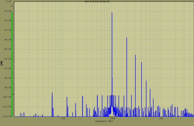 This is the distortion spectrum of the 45 amp with the constant current diodes for the plate load of the driver.
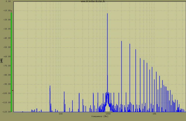 This is the distortion spectrum of the 45 amp with a 10K resistor for the plate load of the driver.
What is important here is that both designs exhibit the same total distortion figures (about 8% at 1.6 watts) but the resistor design has many higher order harmonics. The diode design contains 2nd, 3rd, 4th harmonics. The evil 5th harmonic is 70 db below the fundamental which is pretty much inaudible. To a distortion analyzer or an oscilloscope these two amplifiers are identical, with the FFT analyzer they are not. They definitely don't sound the same either.
When two (or more) signals pass through an amplifier a type of distortion called intermodulation distortion is produced. This can happen in any device that is not perfectly linear. The two signals interact and produce new signals at the sum of the original frequencies and the difference of the original frequencies. Mathematically represented these are IM = f1 + f2 and IM = f1 - f2. There are also third order IM products IM = 2 f1 - f2 and IM = 2 f2 - f1. Higher order IM products may also exist. These new signals are not usually musically related to the original signals, and rarely sound good. Usually both types of distortion exist in any amplifier. This means that all of the intermodulation products will have harmonics.
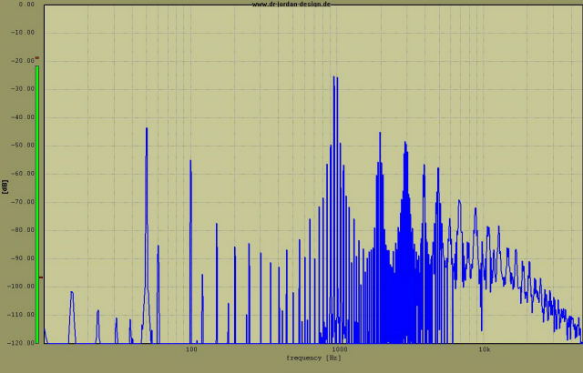 2 Diodes
Above is the FFT plot from an intermodulation test. Here two signals are run through the amplifier at the same time. I ran a 1KHz tone and a 950Hz tone together at the same level (a tough test) through the amplifier, again at 1.6 watts. Ideally that is all you should see at the output of the amp. In the first plot (45 amp with diodes) you see all of the usual harmonics but you will also see a strong signal at 50Hz. This is generated when the 1000Hz and the 950Hz mix with each other in some nonlinear component. You will also notice all of the usual harmonics of the 50Hz signal are present. The 1000Hz and the 950Hz signals also mix to create a signal at 1950Hz, which also contains all of the usual harmonics. None of these new signals are musically related to the original signal. Since music can contain multiple signals at constantly changing amplitudes it is easy to see how a little intermodulation can really cloud up the sound.
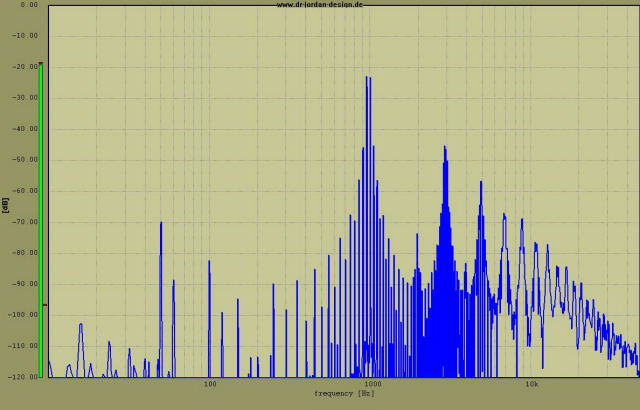 Resistor added in series with the diodes
The above plot on was taken after a 10K pot was installed in series with the diodes and adjusted for the best compromise between intermodulation distortion and the lowest level of higher order distortion. Over a 30db reduction in intermodulation was achieved by adding this resistor. This would go unnoticed with conventional test equipment. I believe an IMD analyzer would find this but I do not have one.
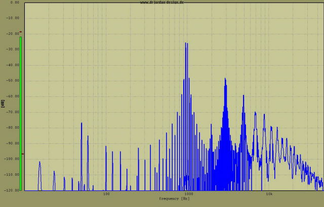 After tweaking the operating point
This plot shows a further reduction in IMD by increasing the supply voltage and lowering the current through the 45 to keep the dissipation below 10 watts. Listening test revealed that the tweaks that reduced the IM distortion also resulted in improved sound. The difference in sound between the first and second plot was dramatic. I am sure that tweaking by ear would have eventually produced the same results however it would take considerable time. All of the tweaks presented here (and several minor ones not shown) took three hours and this was the first time that I have used this software.
The usual frequency response plots are also easy. The plot below shows the frequency response of this amp goes from 10Hz to 22KHz at 1.6 watts. It should be noted that the output transformer being used was designed for an 845 at 25 watts. I hope it works this good when the O2 is finally finished.
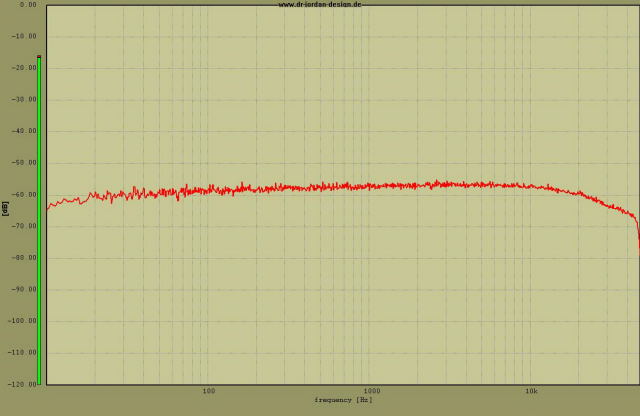 Frequency response