Table of Contents
Resistors
The resistors can be installed on the top side or on the bottom side of the board. Separate instructions are provided for either choice.
The resistors are installed first on the board. Many of them are the smallest components used in this design and they can be difficult to install once the larger components, especially the tube sockets, have been installed. They are also the easiest to install, since they are relatively immune to damage from excessive soldering heat. I recommend installing the resistors in numerical order beginning with R1 and ending with R217. Some builders prefer to install all of the like valued resistors at the same time, going out of sequence. I find that this increases the probability of error, and doesn't save much time. I also recommend printing out the check list, and checking off each part as it is installed. Resistors have no polarity and may be installed in either direction. Some builders will take the time to face all the resistors in the same direction. I do not have the patience for that, but it is perfectly acceptable. Pictures are provided for all of the steps.
The question was asked by Tubelab SSE builders, why the resistors are installed on the top side of the board when using the inverted assembly method. The reason that this is done is to reduce the chance of build error. There are more resistors than all other components combined. There is no silk screening on the back side of the board. It would be easy to get a resistor in the wrong holes, and since they are mostly small parts, inverted mounting is not needed. Once the resistors are mounted, the holes for the other parts are more obvious since there are fewer empty holes. There is no technical reason why the resistors couldn't be placed on the back side, and this could be done with the large ones, or all of them if desired. I have provided inverted build instructions for those who choose to use this method.
The components were numbered according to their function in the design. Resistors R1 through R4 are part of the power supply. R200 through R217 are part of the right channel amplifier circuit, and R100 through R117 are part of the left channel amplifier circuit. For this reason there is no R5 through R99 and R118 through R199.
Five different physical sizes of resistors are used on this board. The physical size is related to the amount of power each resistor can dissipate. Each resistor is also available is varying tolerance values. This is the measure of how close the resistor is to its stated value.
The largest are the 5 watt wire wound resistors used for R1, R112, R116, R212 and R216. These are usually white ceramic cased rectangular parts. They are shown in the photos below. It is possible for these to be round and come in a different color with black being the most common. These usually come in 5% and 10 % tolerance values. The resistance, power rating and tolerance is usually written on the case.
There are 1 watt, 2 watt, and 3 watt carbon film resistors used on this board. A 3 watt resistor is shown below in the R2 picture. R3 is a 1 watt resistor, and R4 is a 2 watt resistor. These are usually blue, grey, or tan in color with 4 color bands to mark the resistance and tolerance value. The power rating is determined by the physical size, and no standard sizes exist.
There are also many smaller sized resistors used on this board. These may be 5% or 1% in tolerance, and 1/4 or 1/2 watt power rating. Any of the 4 possible combinations may be used on this board. They may be marked in two possible ways. The 5% resistors are marked with 3 color bands for the resistance value, and a gold band to designate the 5% tolerance value (4 colored bands total). The 1% resistors have 4 color bands for the value, and a brown band to designate the 1% tolerance value (5 bands total).
Familiarize yourself with the different sizes of resistors before installing any of them. In this design there are different sized resistors with the same resistance value (R2 and R4 are both 150K but different size, this was dictated by the PC board layout). It would be a good idea to identify the resistor used in each component location, and verify its fitment in the PC board before beginning any assembly. It may be helpful to pre-bend the leads of all of the resistors and sort them into a small tray for easy identification during board assembly. Old ice cube trays are useful for this.
If you are going to use the inverted assembly method but place the resistors on the top, it is important that all of the resistors are close to (but not touching) the PC board. When the PC board is mounted to the chassis top plate, there will be about 1/2 inch from the board to the metal plate. There must be sufficient clearance between the components and the grounded chassis plate. Even though the resistors (and other components) have an insulating coating, they should not be in contact with ANY conductive surface, or other components. This is also true for conventional point to point construction. Over time, heat and vibration will eventually break down the insulating coating. If any of your particular resistors are too big for this, mount them on the back side of the PC board.
Begin installing the resistors using the technique shown in the Getting Started page.
Conventional (top side) Assembly
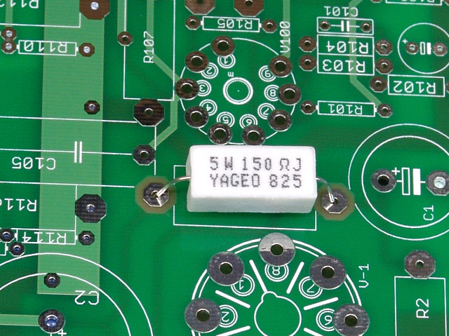 R1 is only used if a power supply choke is NOT being used. This resistor may be a different value in some builds. Consult the parts list before building. If you are using R1, insert and solder it as shown. Clip the excess leads from the part after soldering. If you are not using R1, leave these holes empty, no component is installed in the location for R1. If you are still undecided, leave it out. It can be easily added later.
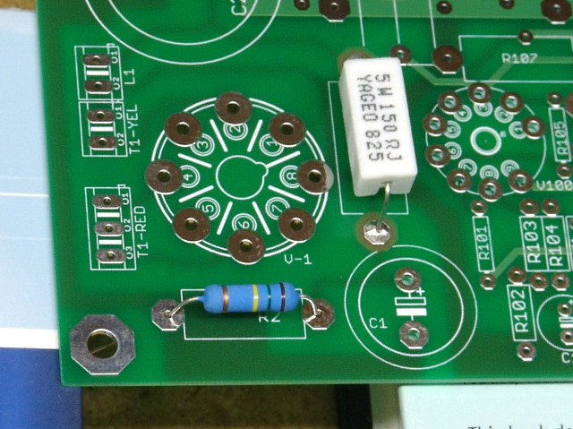 Next insert and solder R2. Note that R2 is a 150K (150,000 ohms) 3 watt resistor. If a 150 ohm resistor is accidentally installed here, the rectifier tube will have a short unhappy life!
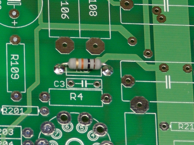 Next insert and solder R3.
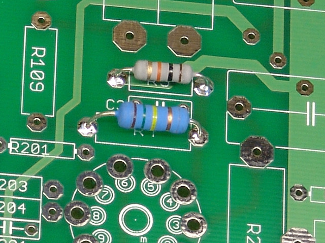 Next insert and solder R4.
There is no R5 through R99 in this design. The next resistor is R100.
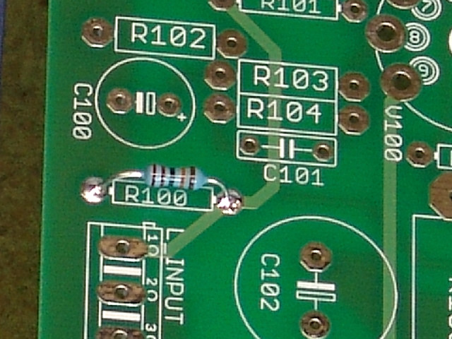 Install R100 as shown. A 1% metal film resistor is shown here.
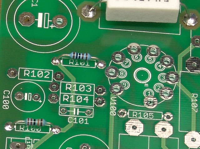 Insert and solder R101.
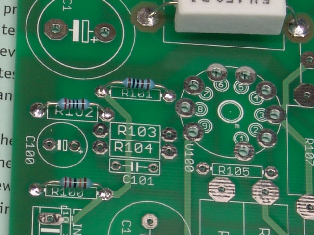 Insert and solder R102.
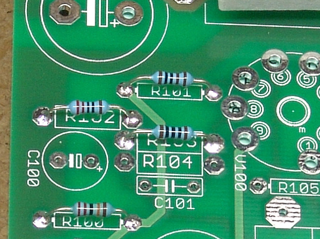 Insert and solder R103.
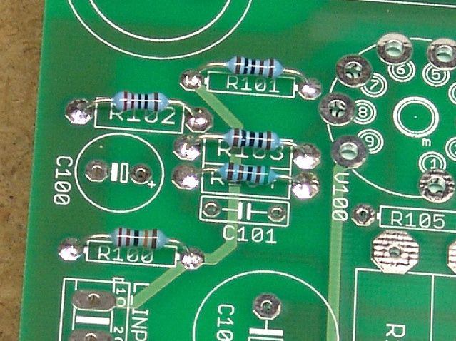 Insert and solder R104. Be careful not to allow solder to bridge to the adjacent pads for R103.
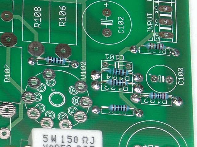 Insert and solder R105.
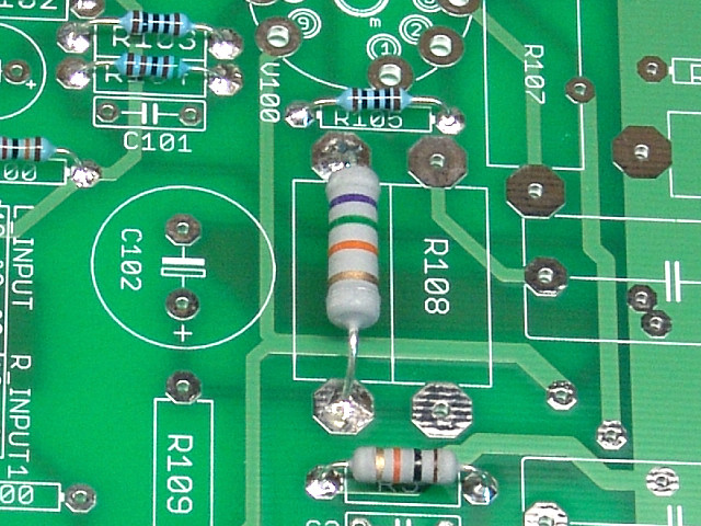 Insert and solder R106.
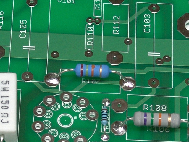 Insert and solder R107.
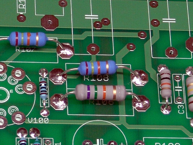 Solder R108 in place. The large pad on the left is very close to R105. Use care to avoid a short.
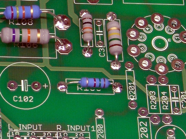 Insert and solder R109.
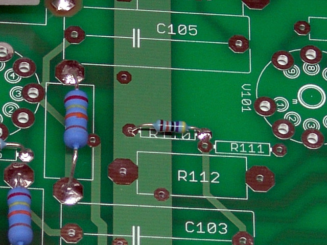 Insert and solder R110.
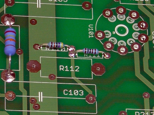 Insert and solder R111. It shares the pads with R110 so a solder bridge here is normal.
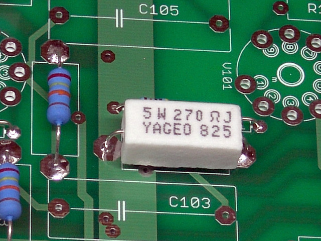 Insert and solder R112.
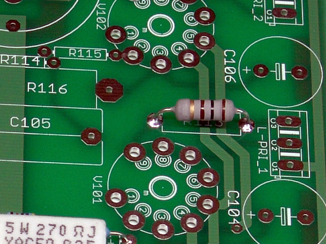 Insert and solder R113.
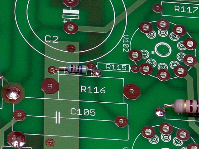 Insert and solder R114.
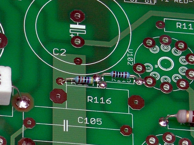 Insert and solder R115.
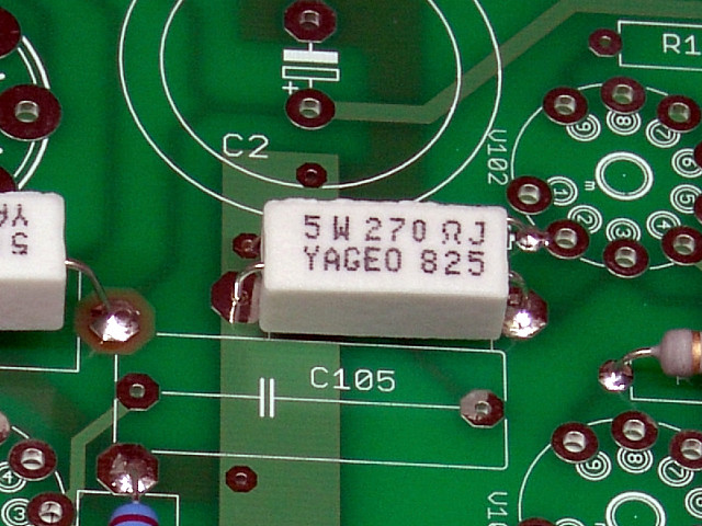 Insert and solder R116.
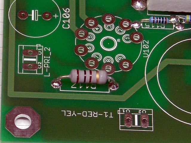 Insert and solder R117.
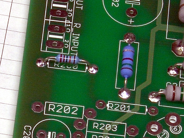 Insert and solder R200.
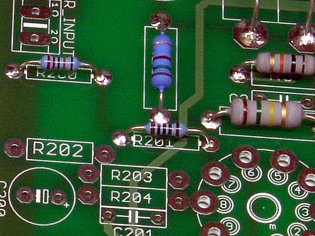 Insert and solder R201.
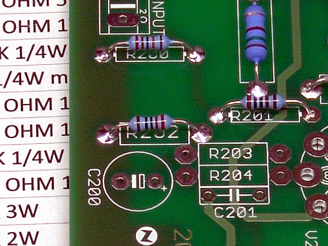 Insert and solder R202.
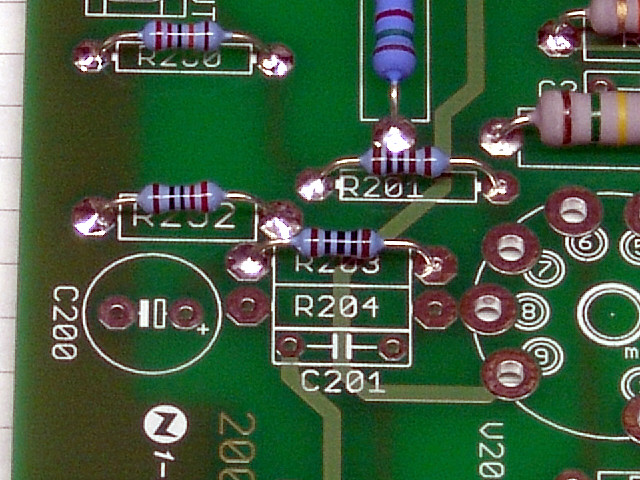 Insert and solder R203.
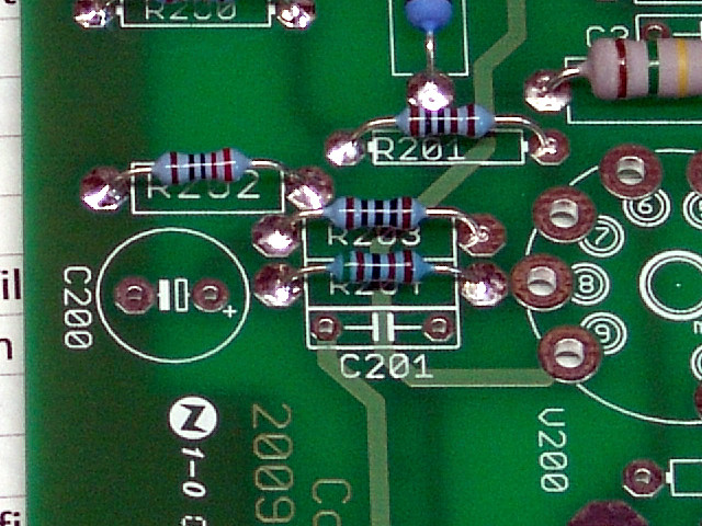 Insert and solder R204. Use caution to avoid solder shorting to R203.
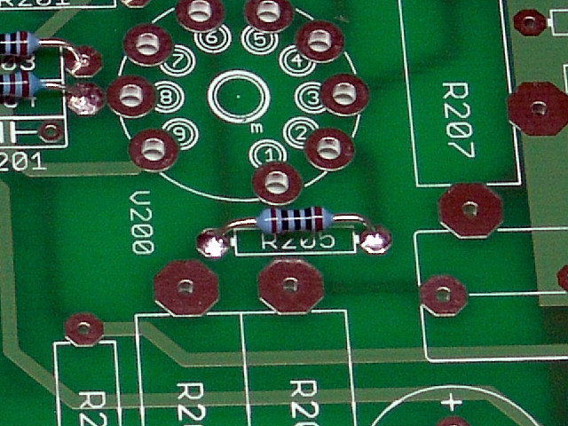 Insert and solder R205.
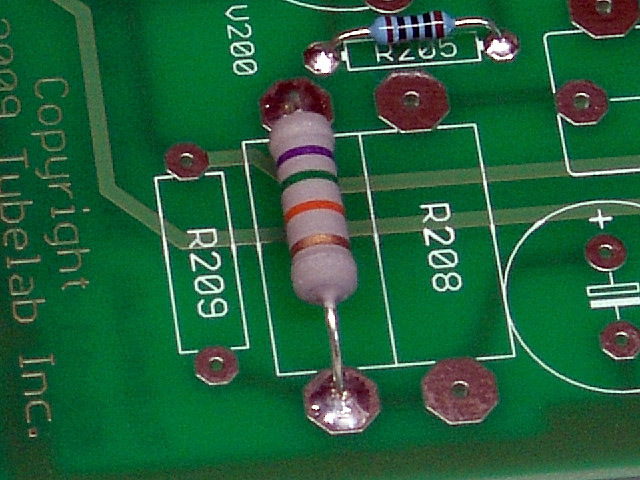 Insert and solder R206.
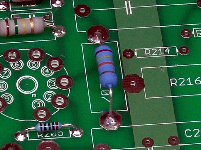 Insert and solder R207.
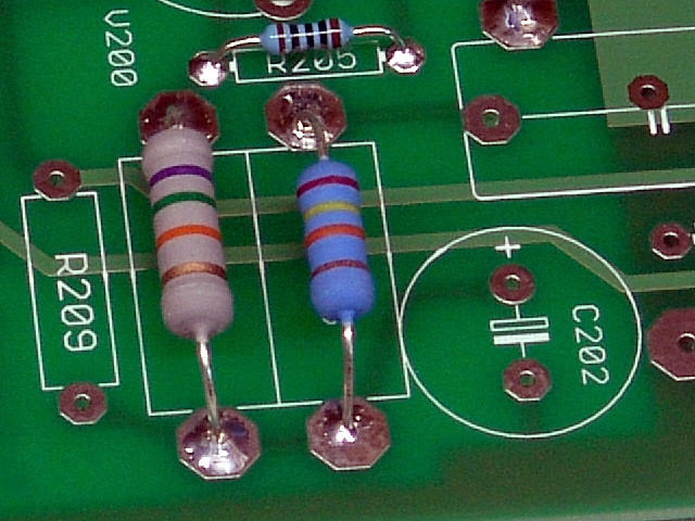 Insert and solder R208.
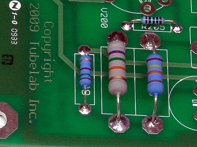 Insert and solder R209.
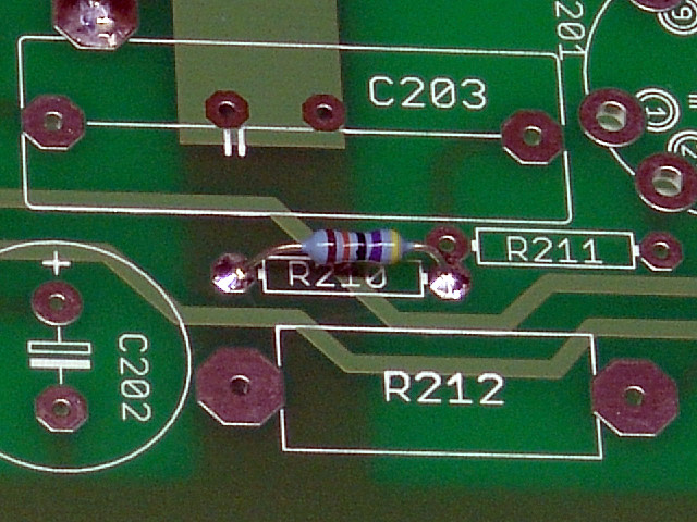 Insert and solder R210.
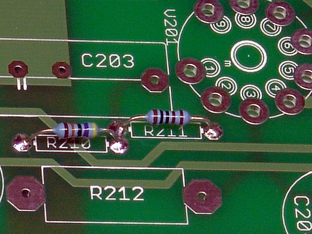 Insert and solder R211. R211 shares the pad with R210. A solder bridge here is normal.
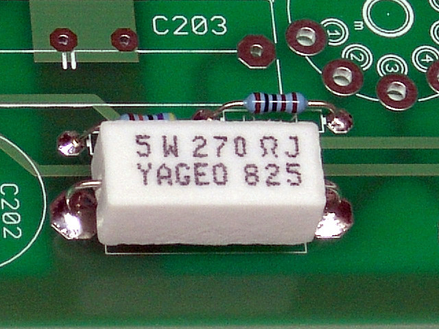 Insert and solder R212.
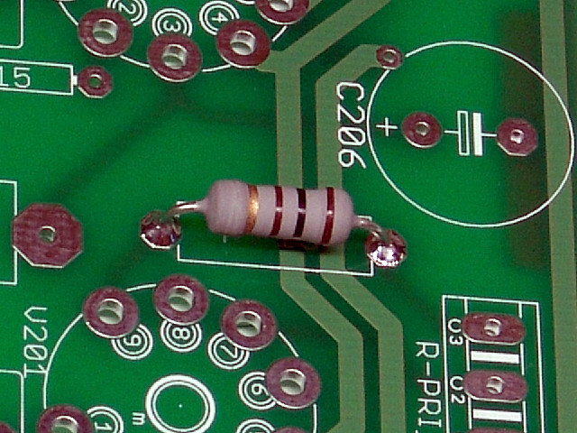 Insert and solder R213.
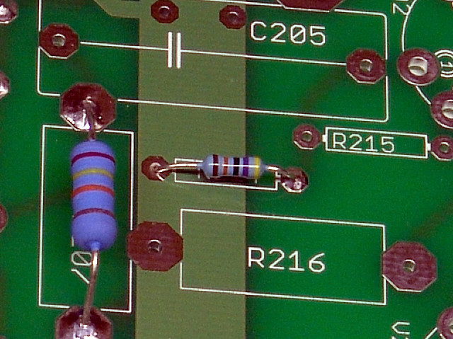 Insert and solder R214.
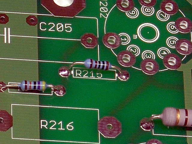 Insert and solder R215.
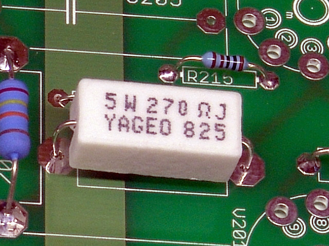 Insert and solder R216.
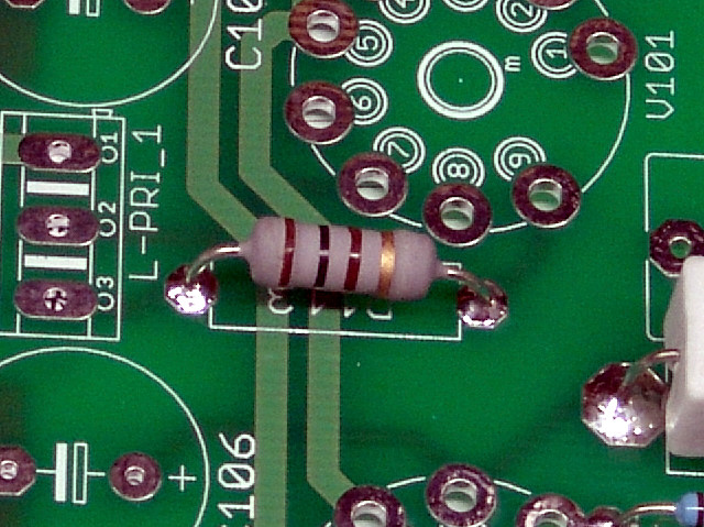 Insert and solder R217.
At this point all of the resistors are installed. Verify that you have installed them all, and all have been checked off on the parts list.
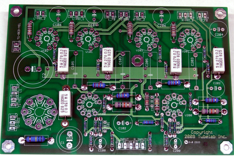
You are now done with the resistors. Please check over your board. Your board should look like this at this point. Your parts may look different than these, but there should be parts in all of these places, and none in any other places.
If your board agrees with the photo, proceed to the tube sockets page.
Inverted (bottom side) Assembly
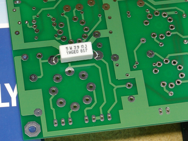 R1 is only used if a power supply choke is NOT being used. This resistor may be a different value in some builds. Consult the parts list before building. If you are using R1, insert and solder it as shown. Clip the excess leads from the part after soldering. If you are not using R1, leave these holes empty, no component is installed in the location for R1. If you are still undecided, leave it out. It can be easily added later.
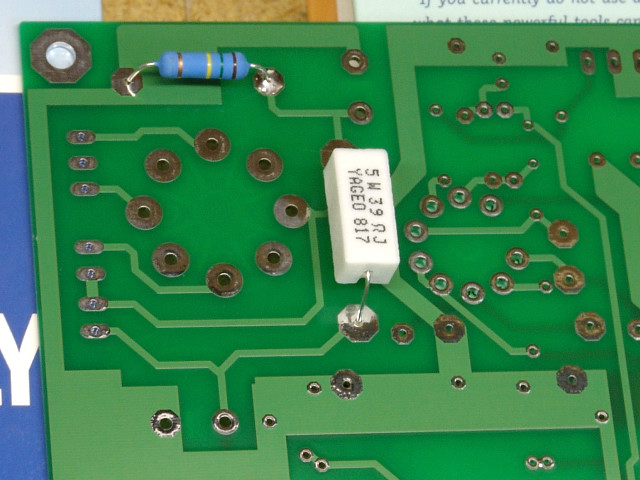 Next insert and solder R2. Note that R2 is a 150K (150,000 ohms) 3 watt resistor. If a150 ohm resistor is accidentally installed here, the rectifier tube will have a short unhappy life!
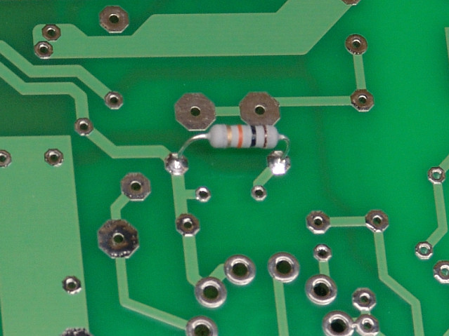 Next insert and solder R3.
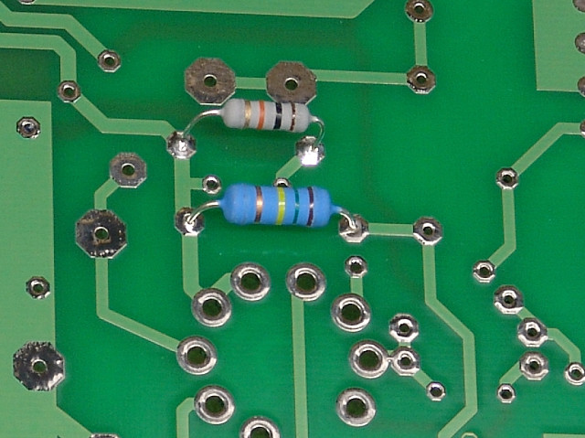 Next insert and solder R4.
There is no R5 through R99 in this design. The next resistor is R100.
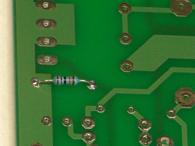 Install R100 as shown. A 1% metal film resistor is shown here.
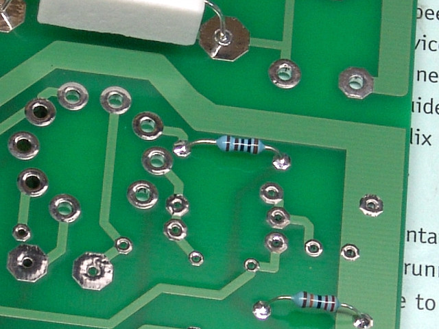 Insert and solder R101.
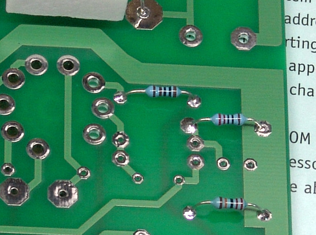 Insert and solder R102.
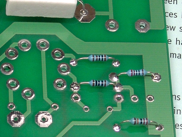 Insert and solder R103.
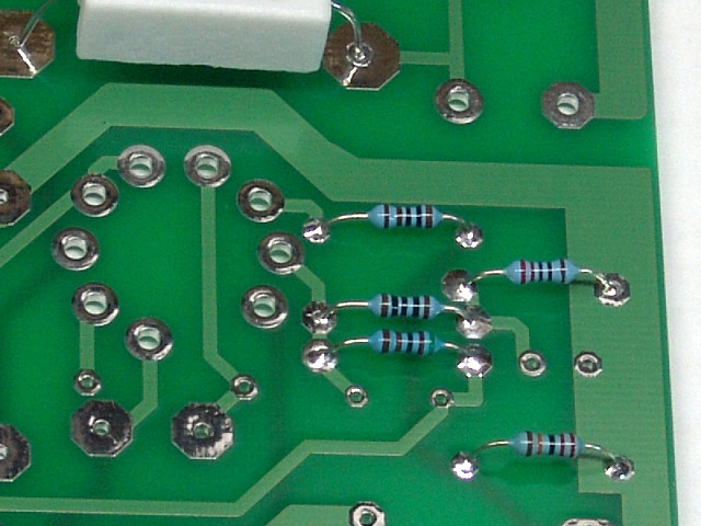 Insert and solder R104. Be careful not to allow solder to bridge to the adjacent pads for R103.
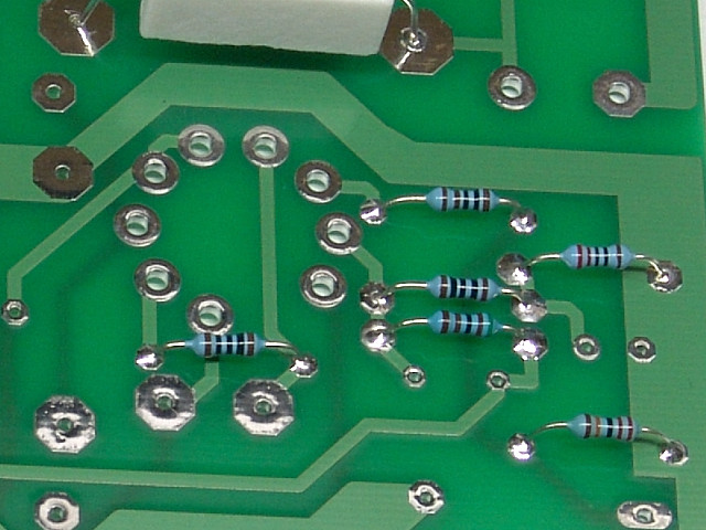 Insert and solder R105.
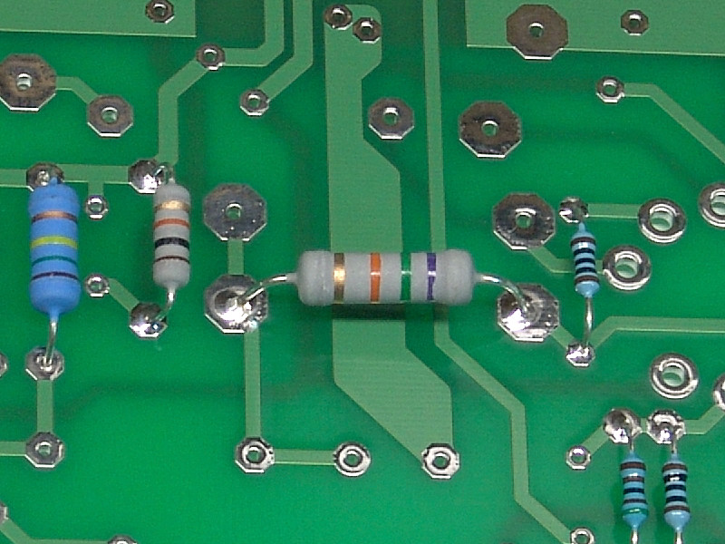 Insert and solder R106.
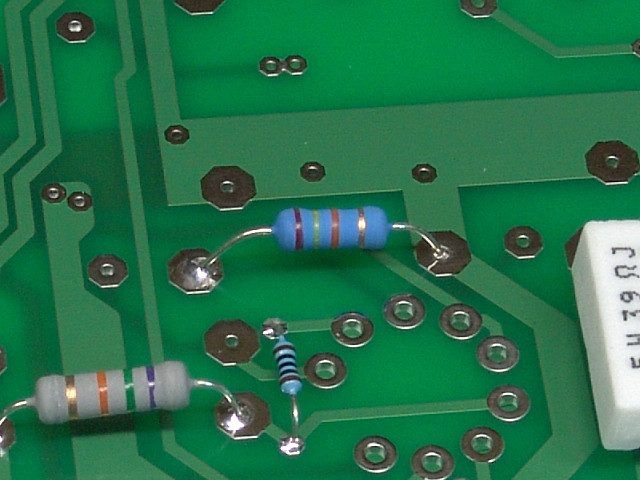 Insert and solder R107.
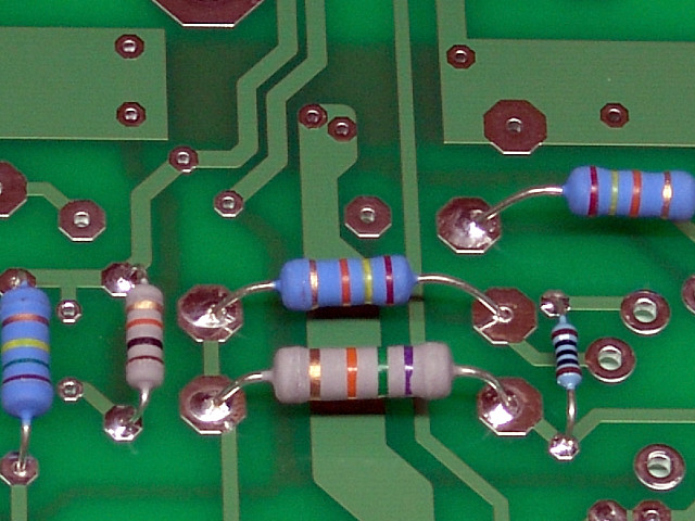 Solder R108 in place. The large pad on the right is very close to R105. Use care to avoid a short.
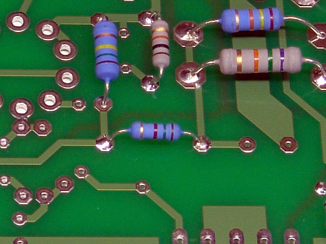 Insert and solder R109.
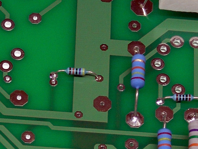 Insert and solder R110.
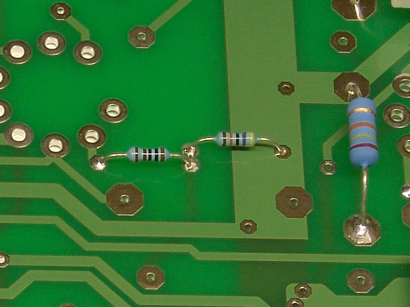 Insert and solder R111. R111 shares the pad with R110 a solder bridge here is normal.
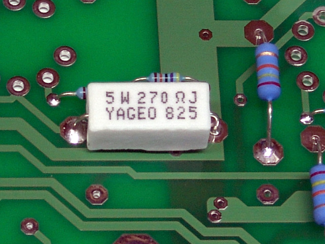 Insert and solder R112.
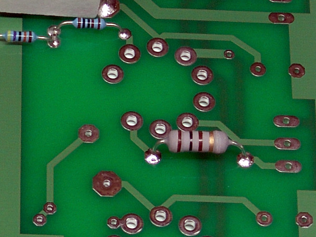 Insert and solder R113.
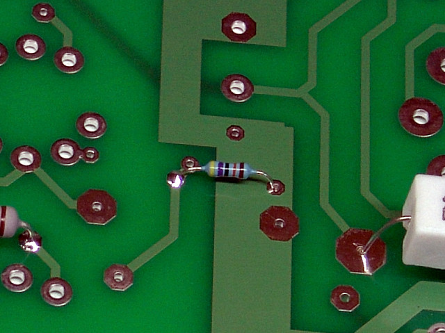 Insert and solder R114.
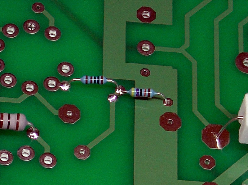 Insert and solder R115.
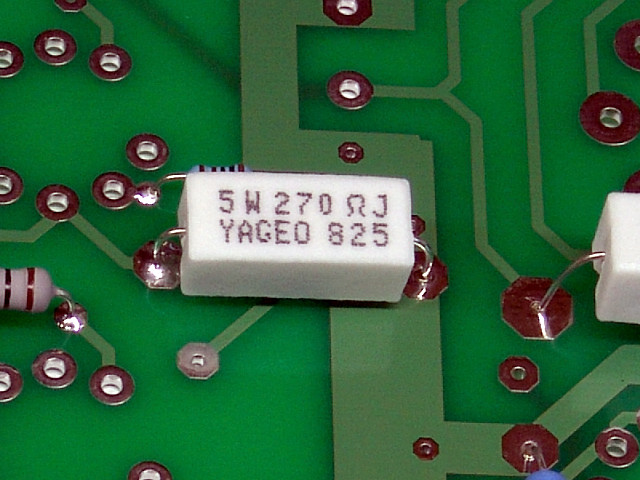 Insert and solder R116.
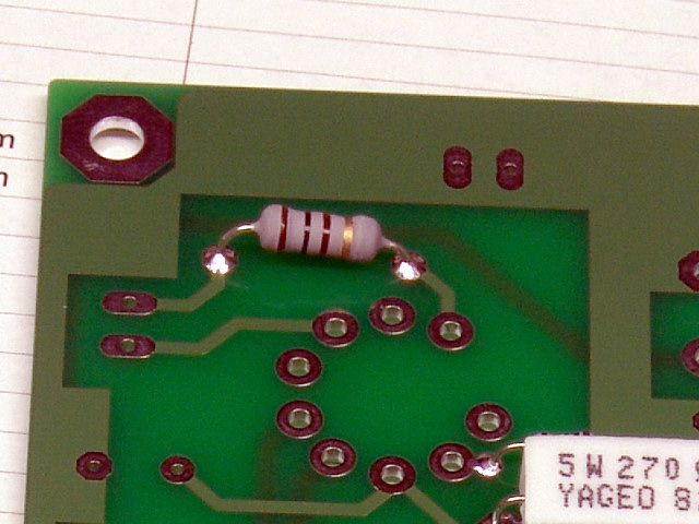 Insert and solder R117.
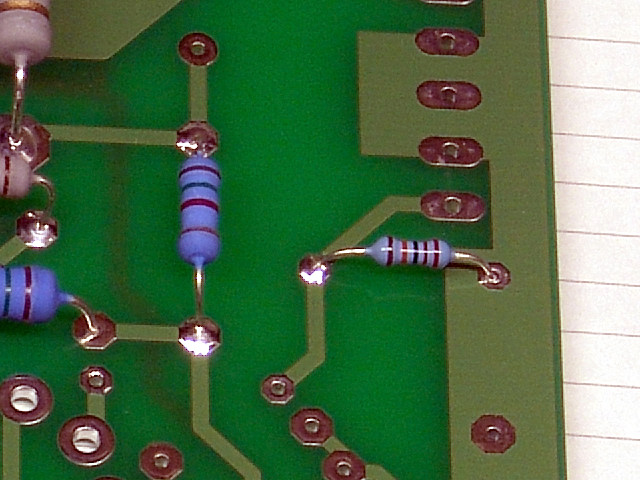 Insert and solder R200.
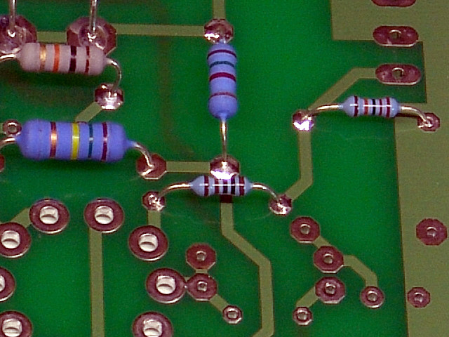 Insert and solder R201.
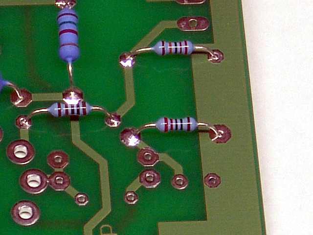 Insert and solder R202.
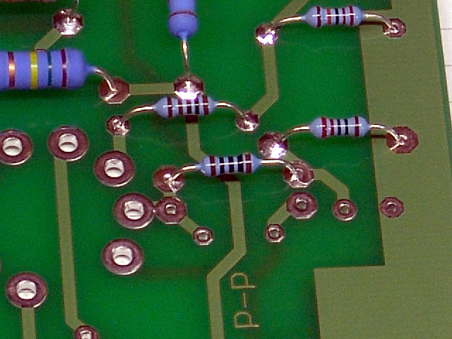 Insert and solder R203.
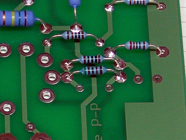 Insert and solder R204. Use caution to avoid a solder short with R203.
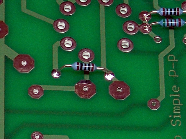 Insert and solder R205.
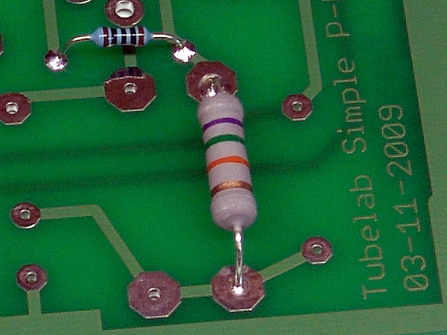 Insert and solder R206.
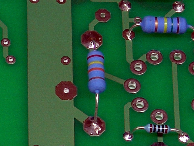 Insert and solder R207.
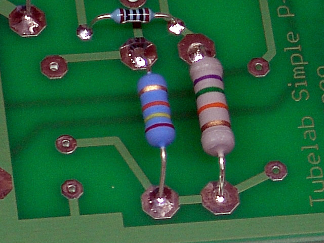 Insert and solder R208.
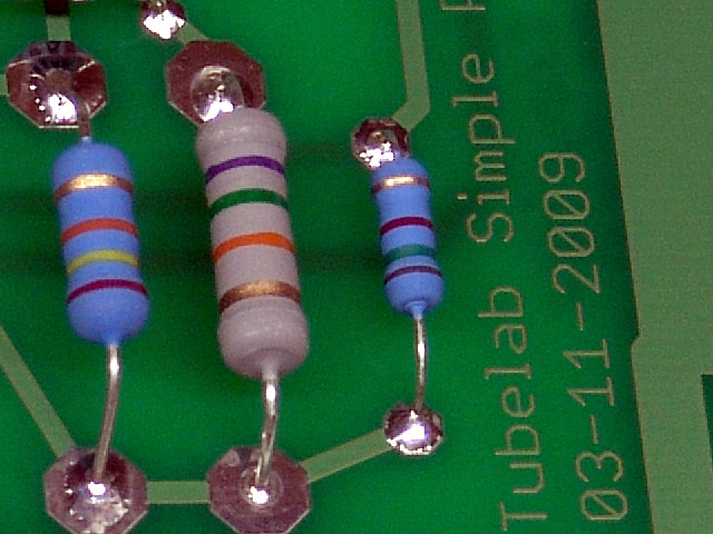 Insert and solder R209.
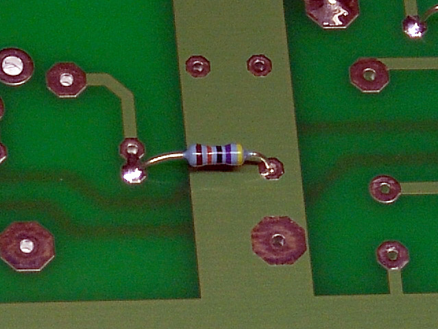 Insert and solder R210.
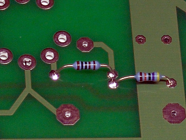 Insert and solder R211. R211 shares the pad with R210. A solder bridge here is normal.
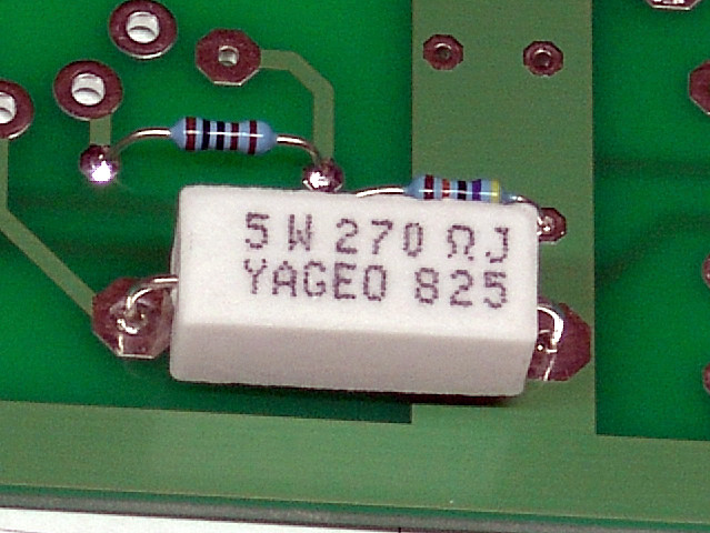 Insert and solder R212.
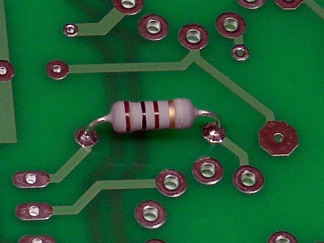 Insert and solder R213.
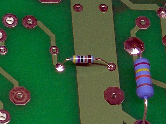 Insert and solder R214.
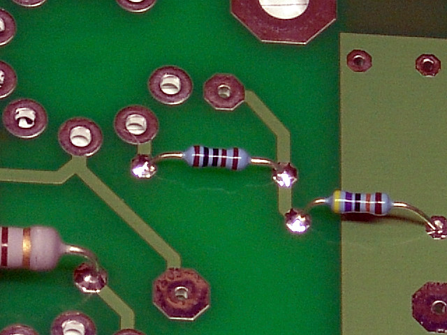 Insert and solder R215.
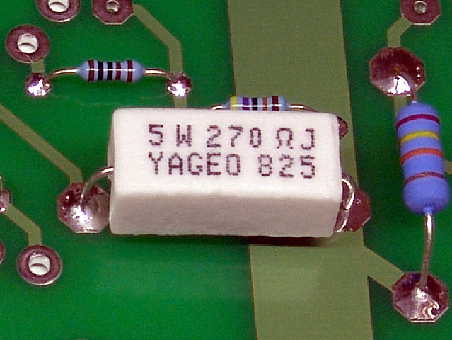 Insert and solder R216.
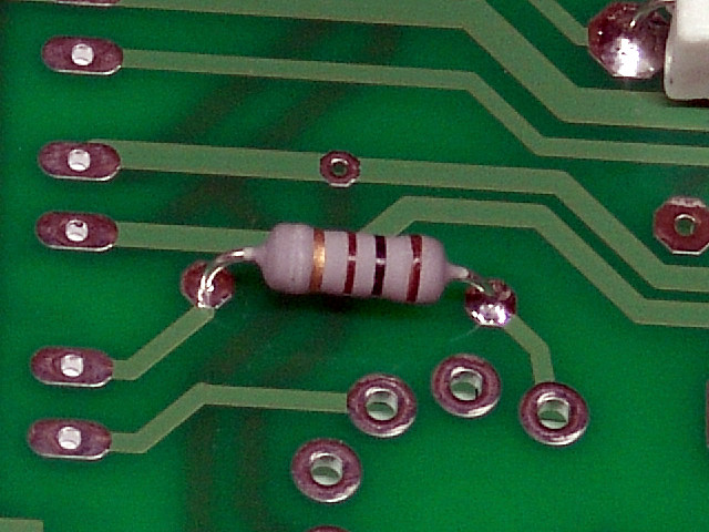 Insert and solder R217.
At this point all of the resistors are installed. Verify that you have installed them all, and all have been checked off on the parts list.
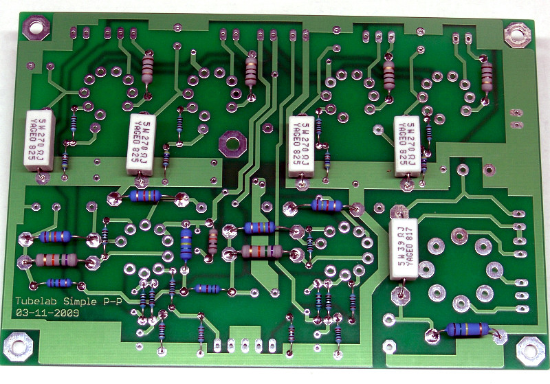
You are now done with the resistors. Please check over your board. Your board should look like this at this point. Your parts may look different than these, but there should be parts in all of these places, and none in any other places.
If your board agrees with the photo, proceed to the tube sockets page.