Table of Contents
- Getting Started
- Resistors
- Tube Sockets
Connectors
- Capacitors
- Semiconductors
Connectors
This board uses connectors for all off board wiring. This allows the transformers and all other wiring to be done without soldering. This was a highly requested feature on The Tubelab SSE board which was incorporated on this board. Some purists may not want connectors in the audio path (especially at the input). If this applies to you, you may solder wires directly to the PC board. Keep in mind that soldering wires (especially heavy transformer wires) directly to the board has been the greatest cause of ruined boards. I have used these connectors on every board that I have built with no issues. It makes board testing much easier, and doesn't affect the sound.
As with the other large parts the connectors can be mounted on either side of the PC board. There are two sets of instructions, so choose the ones that apply to your particular amp design. In this case the steps are the same on either side of the board, only the pictures change.
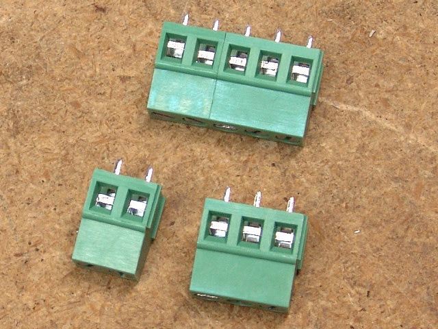
The connectors used on the SPP are modular in design. There are grooves in one edge and ridges on the other edge. This allows two or more of these connectors to be mated to make a larger one, so that 2 and 3 pin connectors can be used to make all sizes. In this board we will "make" a 4 pin and a 5 pin connector.
The photos on this page show the board with the capacitors installed. I discovered that the L-PRI_1 connector is rather hard to support for soldering after the capacitors are installed, since it is between C104 and C106 which are rather tall. This lead to revising the recommended build order after many of these photos were done. Your board should not have the capacitors installed yet.
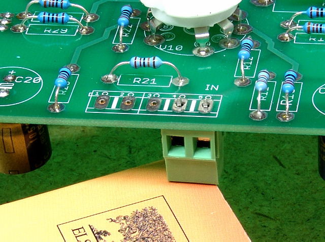
Place the connector in the board. Make sure that the holes for inserting the wire are facing out (away from the board), Flip the board over and rest it on a book or similar object (I used a capacitor) to keep the connector from falling out. Solder it in place. (SSE board shown). This procedure is used for all of the connectors.
Installing the Connectors (bottom side assembly)
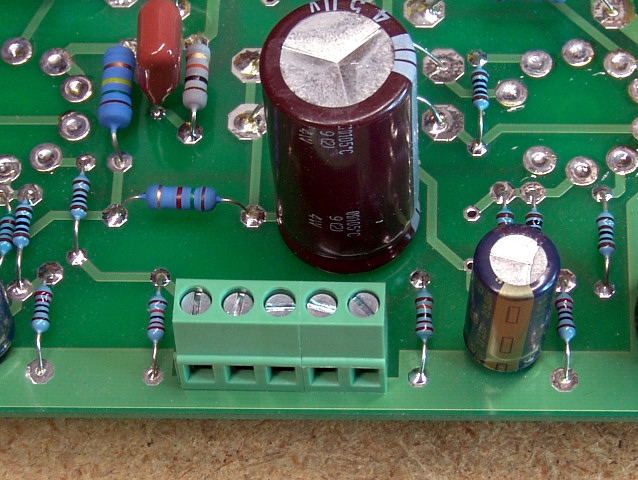 The input connector goes here. There are 5 holes. I joined a 3 pin and a 2 pin connector to make the 5 pin connector. The center 3 holes are all GROUND, so an extra connection is available. Most builds will only use two of them, so two 2 pin connectors can be used leaving the center hole unused if desired.
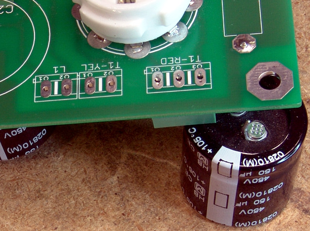 Install a 3 pin connector in the T1-RED position. There is nothing connected to the center pin. Do not use it for any connections. This is needed to assure adequate spacing for the voltages seen on these pins.
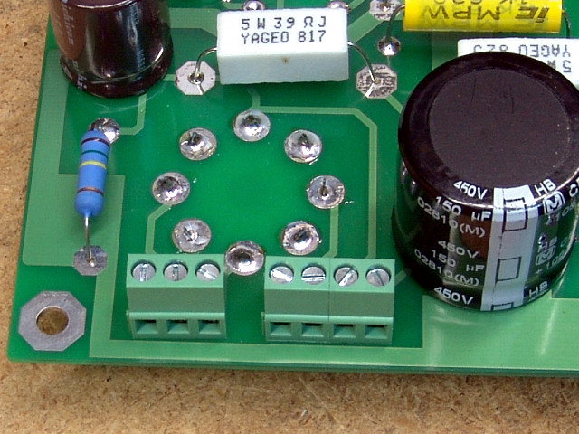 The connectors for T1-YEL and L1 are so close that they can be snapped together and inserted as one 4 pin connector.
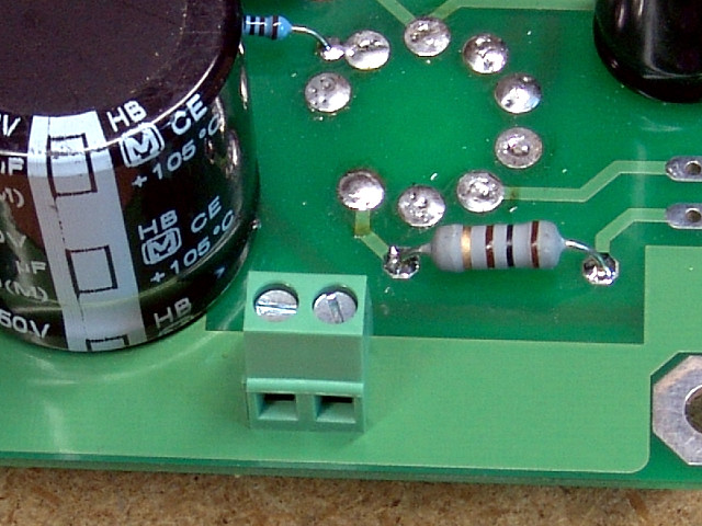 Install a 2 pin connector in the T1-RED-YEL position. Both connections are ground. One will be used for the Red - Yellow wire on the power transformer. The other may or may not be used depending on the final implementation. It does not matter which terminal is used.
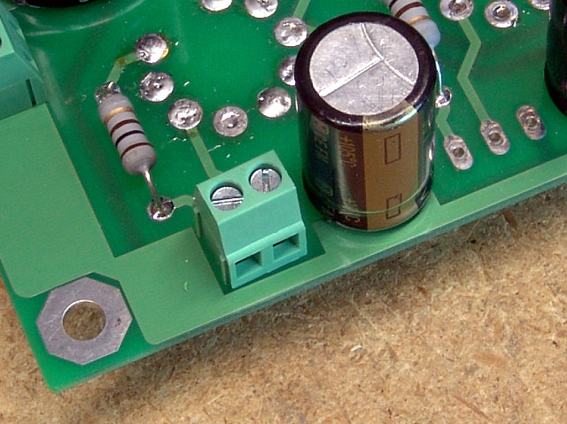 Install a 2 pin connector in the L-PRI_2 position.
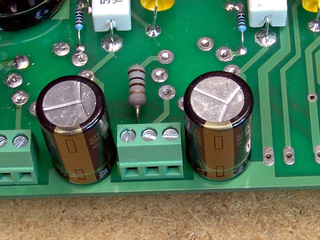 Install a 3 pin connector in the L-PRI_1 position. You can see why the connector needs to go in before the capacitors do.
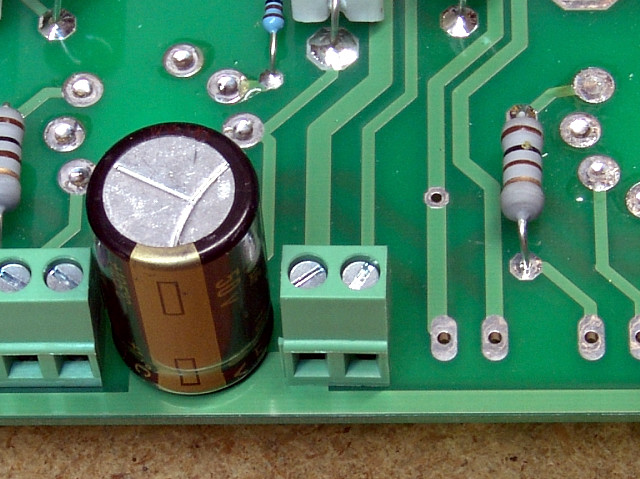 Install a 2 pin connector in the L_FB position.
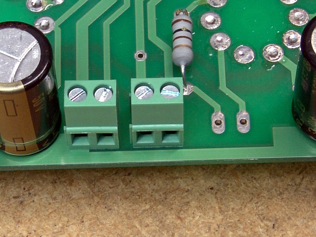 Install a 2 pin connector in the T1-GRN position.
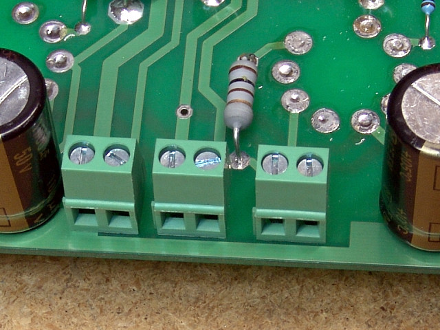 Install a 2 pin connector in the R-PRI_2 position.
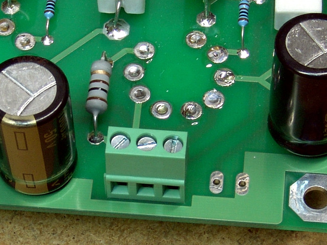 Install a 3 pin connector in the R-PRI_1 position.
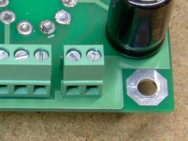 Install a 2 pin connector in the R-FB position.
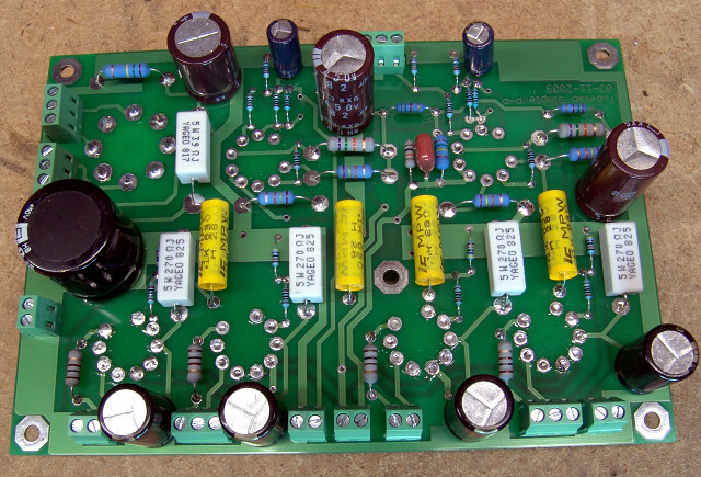 The connectors should look like this when finished. If everything looks OK, proceed to the capacitors page.
Installing the Connectors (top side assembly)
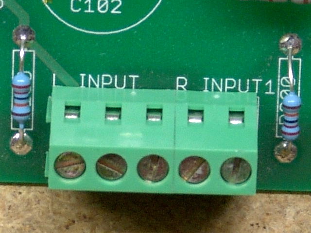 The input connector goes here.
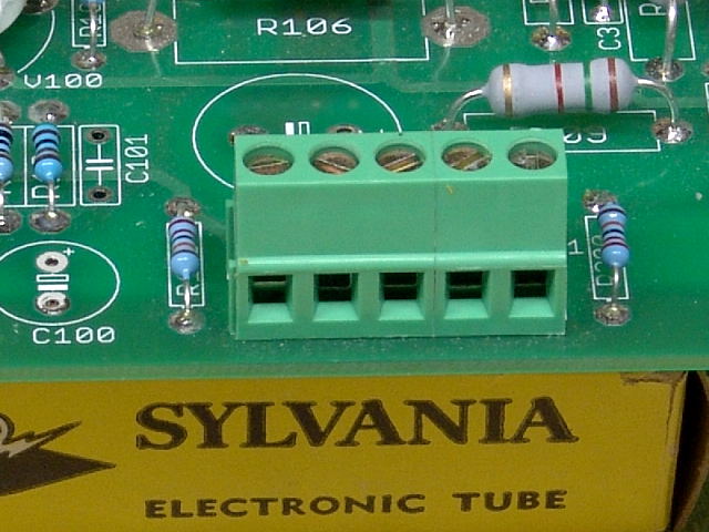 There are 5 holes in the PC board. I joined a 3 pin and a 2 pin connector to make the 5 pin connector. The center 3 holes are all GROUND, so an extra connection is available. Most builds will only use two of them, so two 2 pin connectors can be used leaving the center hole unused if desired.
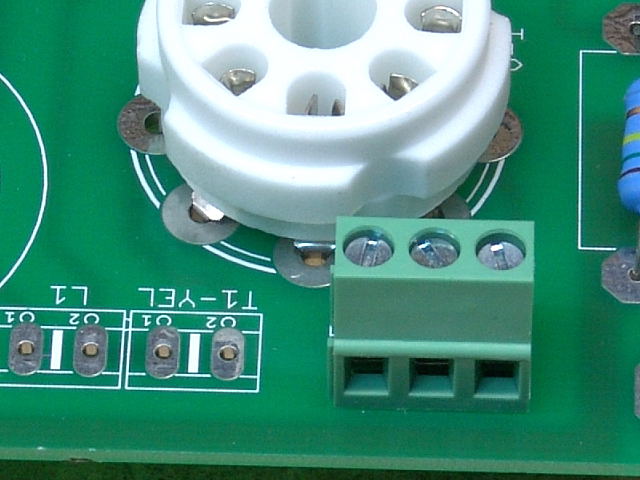 Install a 3 pin connector in the T1-RED position. There is nothing connected to the center pin. Do not use it for any connections. This is needed to assure adequate spacing for the voltages seen on these pins.
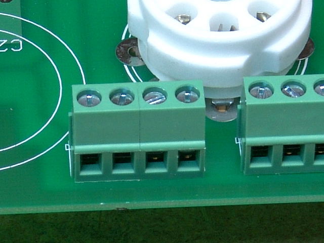 The connectors for T1-YEL and L1 are so close that they can be snapped together and inserted as one 4 pin connector.
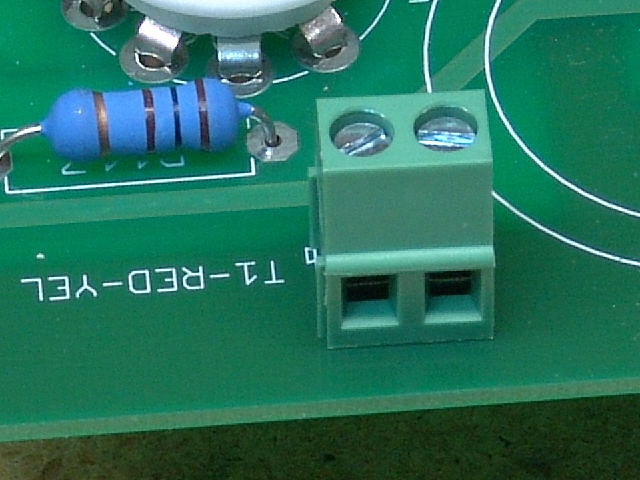 Install a 2 pin connector in the T1-RED-YEL position. Both connections are ground. One will be used for the Red - Yellow wire on the power transformer. The other may or may not be used depending on the final implementation. It does not matter which terminal is used.
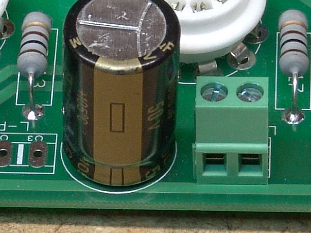 Install a 2 pin connector in the L-PRI_2 position.
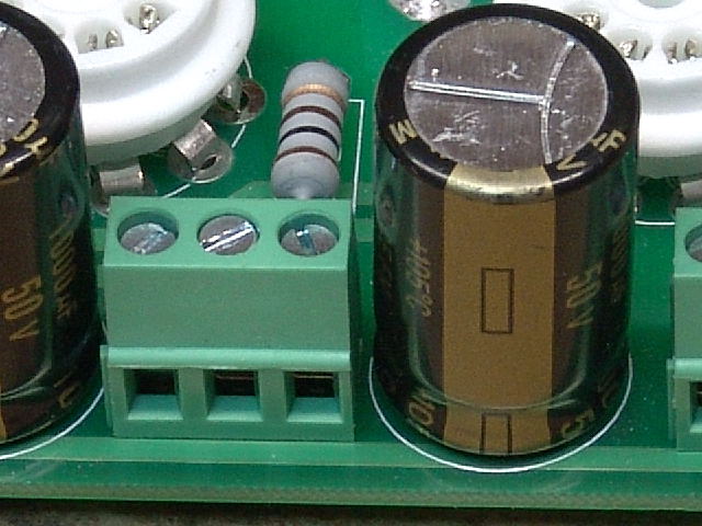 Install a 3 pin connector in the L-PRI_1 position. You can see why the connector needs to go in before the capacitors do.
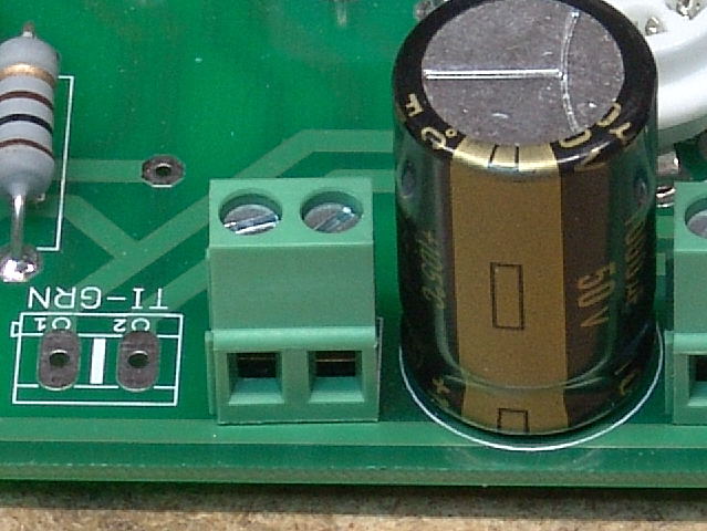 Install a 2 pin connector in the L_FB position.
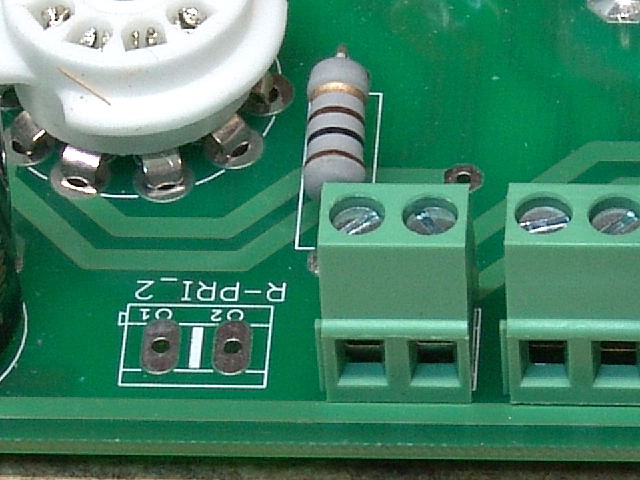 Install a 2 pin connector in the T1-GRN position.
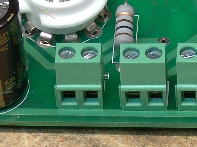 Install a 2 pin connector in the R-PRI_2 position.
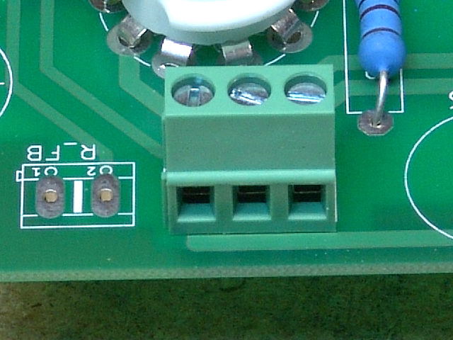 Install a 3 pin connector in the R-PRI_1 position.
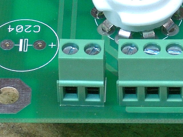 Install a 2 pin connector in the R-FB position.
 The connectors should look like this when finished. If everything looks OK, proceed to the capacitors page.