Table of Contents
- Getting Started
- Resistors
- Tube Sockets
- Connectors
Capacitors
- Semiconductors
Capacitors
There are two sets of assembly instructions on this page. The normal (top side assembly) instructions are first followed by the inverted (bottom side) assembly instructions. Your choice of enclosure for the PC board will dictate which method you use. Choose one method for assembling the board, and follow the same method for the remainder of the board assembly.
Electrolytic capacitors have a polarity and MUST be installed in the correct direction.
There is a + sign on the board silk screen near the positive connection of each electrolytic cap. All electrolytic capacitors will be marked, unfortunately they are not always marked the same. On most current capacitors the NEGATIVE lead is marked with a stripe, which usually contains a minus sign. Most also have a longer lead for the POSITIVE terminal. Some will have marking for one or both terminals on the plastic adjacent to the terminal itself. Make absolutely sure that you identify the terminals on your capacitors before installing them.
If an electrolytic is installed backwards, it WILL fail. The failure is often instant and usually an explosion, often violent, which can cause serious injury. The chemicals contained inside these caps are caustic. They are not good for people, and will eventually eat the plating off of the PC board. This is the most common reason for many amplifiers not working on the first try.
As with the resistors, the capacitors are numbered by function. C1, C2, and C3 are part of the power supply. C100, C101, C102, C103, C104, C105 and C106 are part of the left channel amplifier circuit, while C200, C201, C202, C203, C204, C205 and C206 are part of the right channel amplifier circuit. There is no C4 through C99 and no C107 through C199 in this design.
C101 and C201 are not installed during initial assembly. They may be added later.
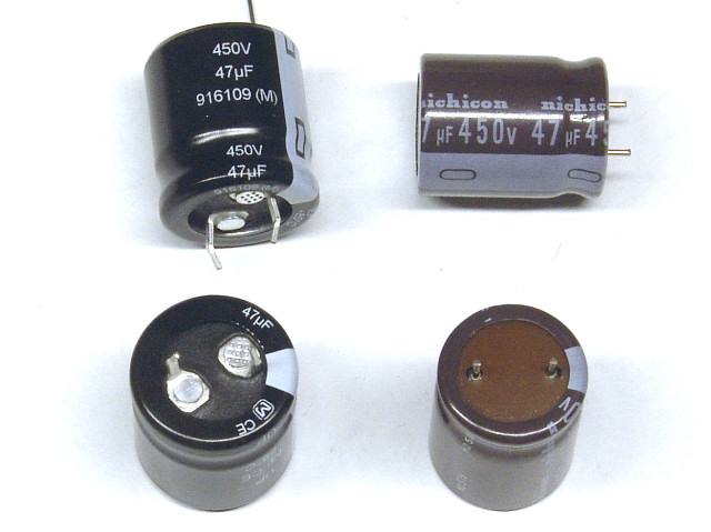
The typical value for C1 puts it at the size where many vendors transition from leaded capacitors to snap in capacitors. Most leaded capacitors have long leads, but some leaded capacitors are furnished with short leads to facilitate their use in automated PC board assembly machines. Any of these are suitable for use in the SPP.
Capacitor Installation (top side assembly)
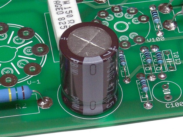 Install C1 as shown. Make sure that the negative side is closest to the edge of the board. This photo shows a Nichicon cap.
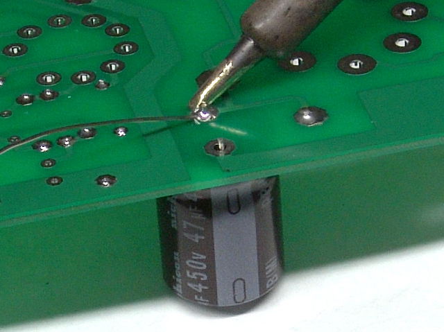 The short leaded caps are installed and soldered like any other component. The leads are smaller than the holes, which are sized for the snap in capacitors. This is much like the tube socket pins.
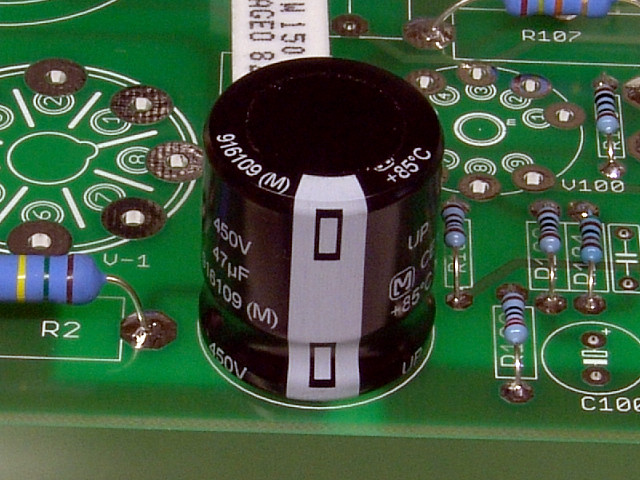 This photo shows a Panasonic cap for C1. Again the negative stripe is closest to the edge of the board.
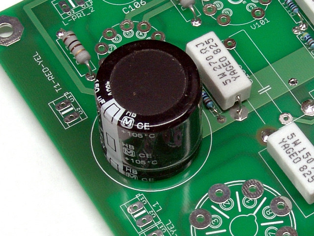 Install C2 as shown. Most capacitors of this size will be the snap in type. Make sure that the negative stripe is closest to the edge of the board as shown.
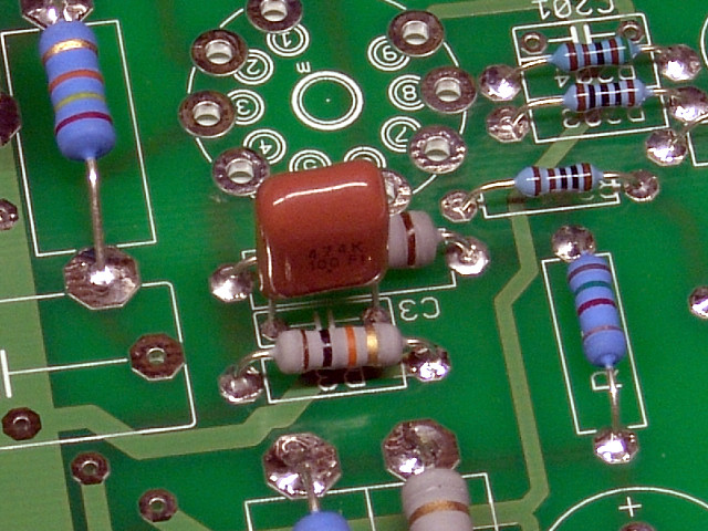 Install C3 as shown. It has no polarity and can be inserted either way.
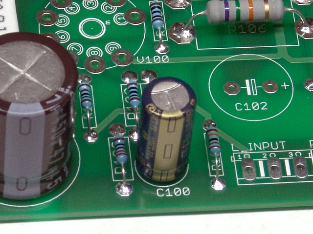 Install C100 as shown. The negative stripe should face the edge of the board.
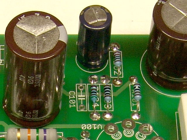 C101 is the feedback compensation capacitor. It is not installed at this time. The value is highly dependent on the type of output transformers that are used. The value can be determined by measurement or listening tests. It may not be needed at all in some builds.
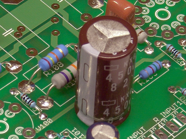 Install C102 as shown. It is polarized and must be installed in the proper direction. The negative stripe faces the empty holes for C101. I have used several different values for C102 and C202. The current parts list may specify a smaller part.
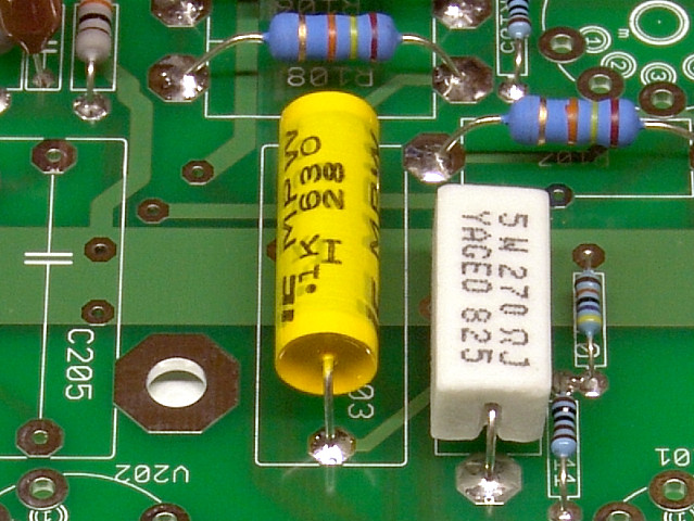 Install C103 as shown. C103 is one of four coupling capacitors. There are dozens of possible choices for the coupling caps. The coupling caps are also a popular upgrade item. If you choose to install a significantly larger cap, make sure that the wires do not touch anything else on the PC board.
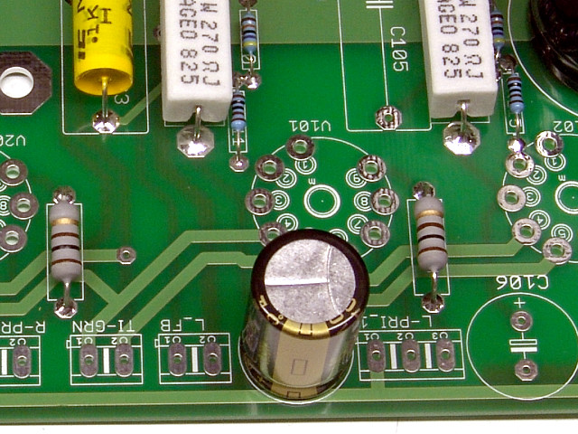 Install C104 as shown. The negative stripe should face the edge of the board.
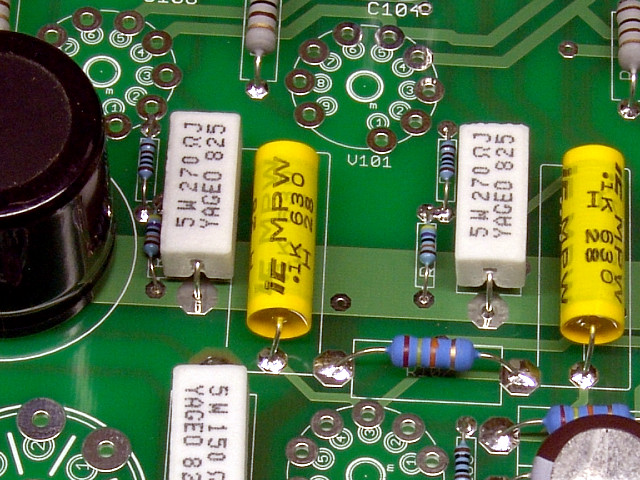 Install C105 as shown. C105 is one of four coupling capacitors.
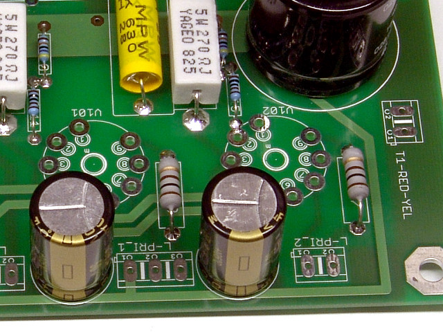 Install C106 as shown. The negative stripe should face the edge of the board.
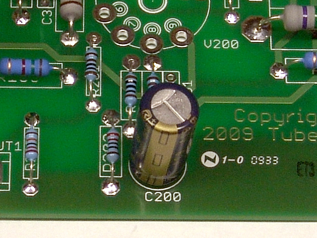 Install C200 as shown. The negative stripe should face the edge of the board.
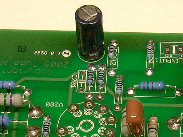 C201 is the feedback compensation capacitor. It is not installed at this time. The value is highly dependent on the type of output transformers that are used. The value can be determined by measurement or listening tests. It may not be needed at all in some builds.
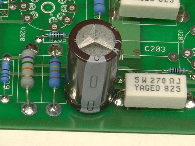 Install C202 as shown. It is polarized and must be installed in the proper direction. The negative stripe faces the edge of the board. I have used several different values for C102 and C202. The current parts list may specify a smaller part.
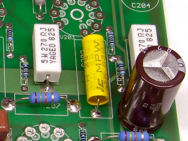 Install C203 as shown. C203 is one of four coupling capacitors.
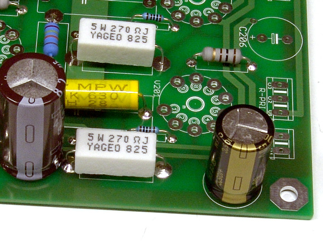 Install C204 as shown. The negative stripe should face the edge of the board.
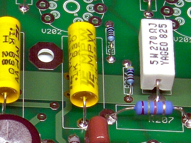 Install C205 as shown. C205 is one of four coupling capacitors.
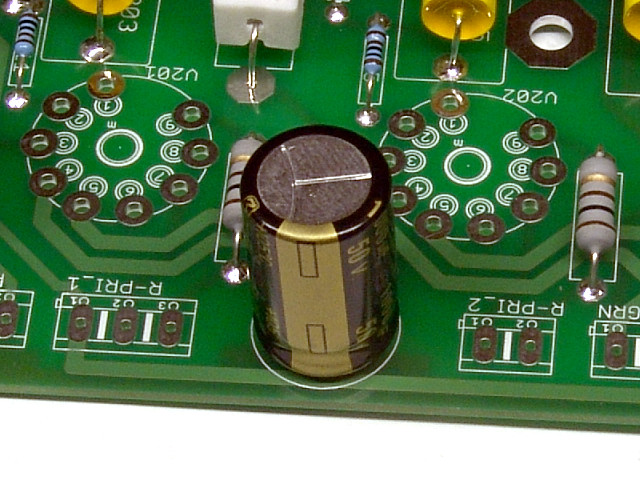 Install C206 as shown. The negative stripe should face the edge of the board
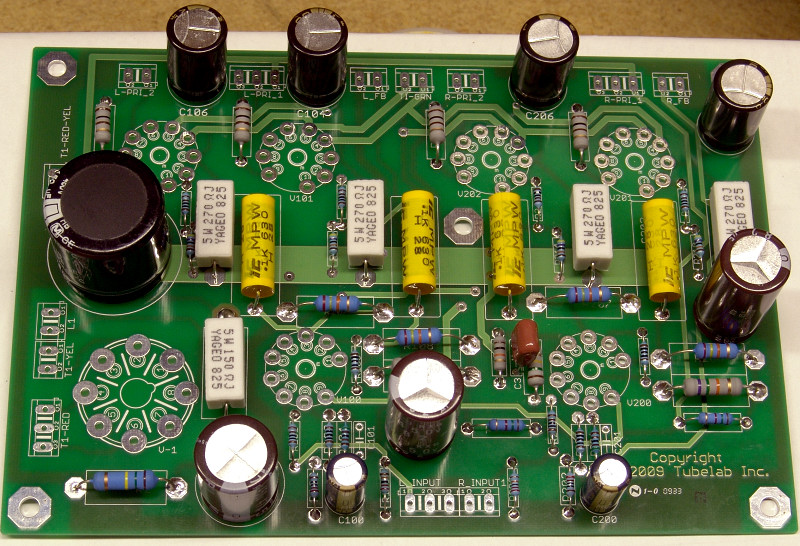 This photo shows a board with all of the capacitors in place. Your board should have all of the components in place at this time.
Capacitor Installation (bottom side assembly)
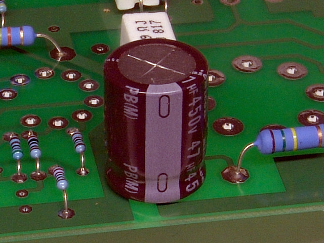 Install C1 as shown. Make sure that the negative side is closest to the edge of the board. This photo shows a Nichicon cap.
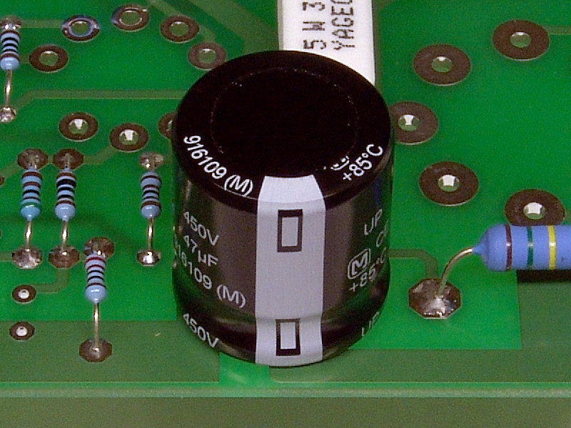 This photo shows a Panasonic cap for C1. Again the negative stripe is closest to the edge of the board.
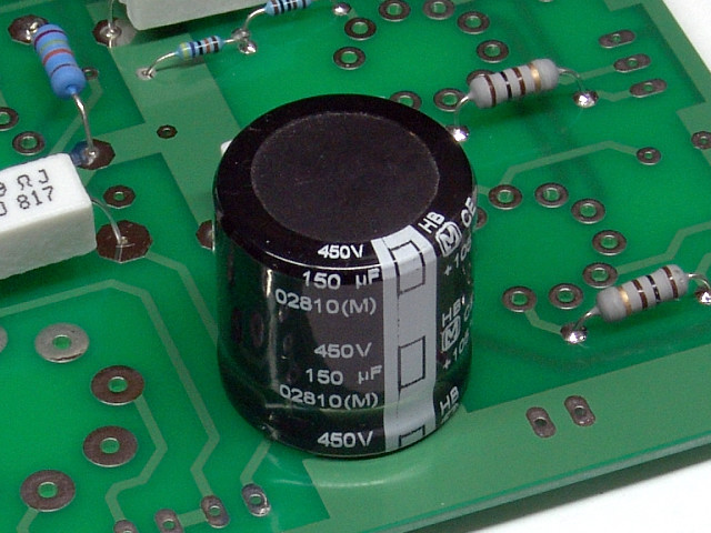 Install C2 as shown. Most capacitors of this size will be the snap in type. Make sure that the negative stripe is closest to the edge of the board as shown.
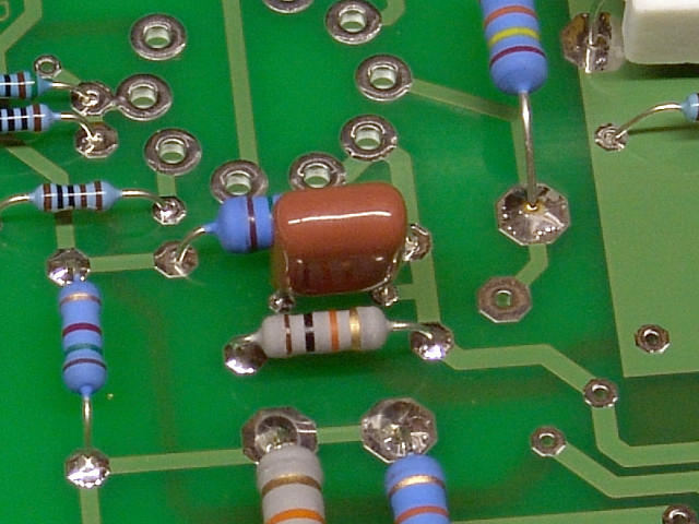 Install C3 as shown. It has no polarity and can be inserted either way.
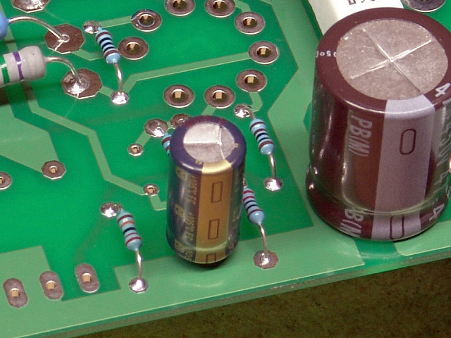 Install C100 as shown. The negative stripe should face the edge of the board.
 C101 is the feedback compensation capacitor. It is not installed at this time. The value is highly dependent on the type of output transformers that are used. The value can be determined by measurement or listening tests. It may not be needed at all in some builds.
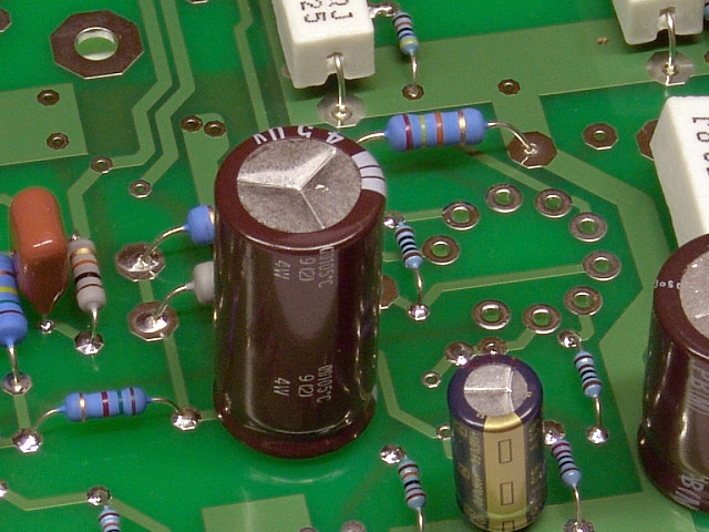 Install C102 as shown. It is polarized and must be installed in the proper direction. The negative stripe faces the empty holes for C101. I have used several different values for C102 and C202. The current parts list may specify a smaller part.
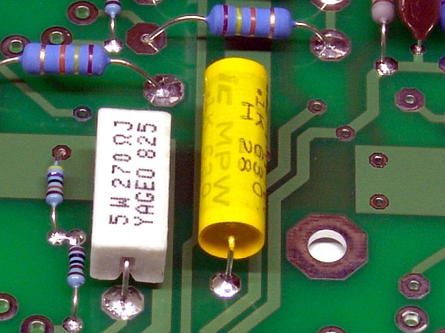 Install C103 as shown. C103 is one of four coupling capacitors. There are dozens of possible choices for the coupling caps. The coupling caps are also a popular upgrade item. If you choose to install a significantly larger cap, make sure that the wires do not touch anything else on the PC board.
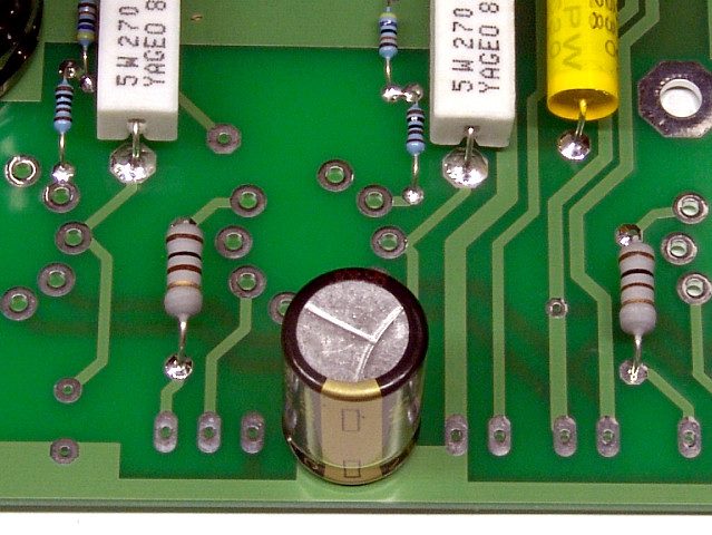 Install C104 as shown. The negative stripe should face the edge of the board.
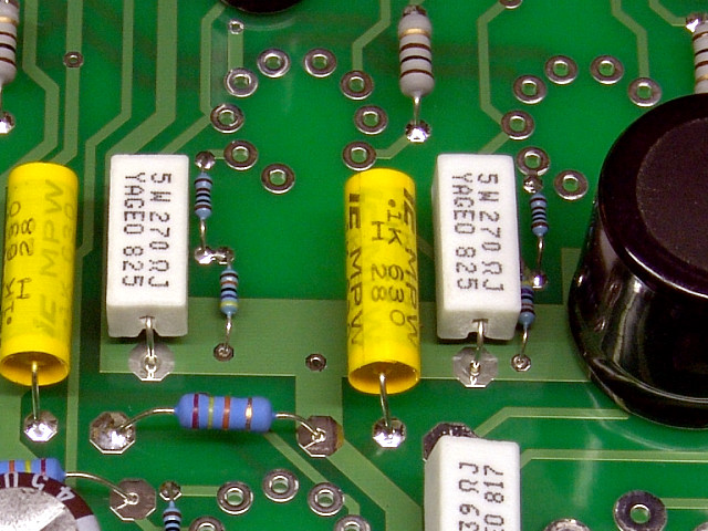 Install C105 as shown. C105 is one of four coupling capacitors.
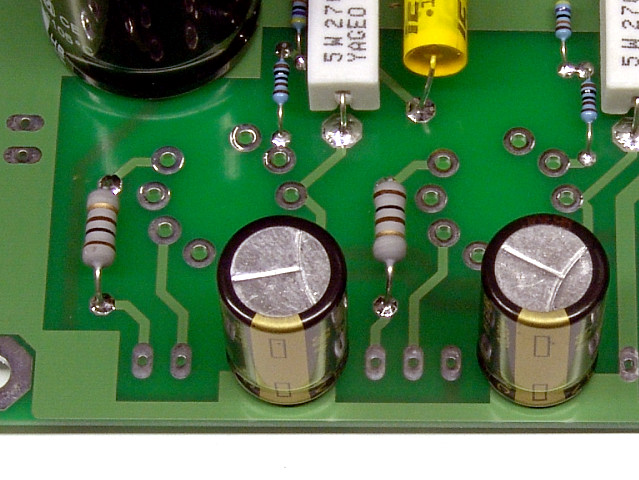 Install C106 as shown. The negative stripe should face the edge of the board.
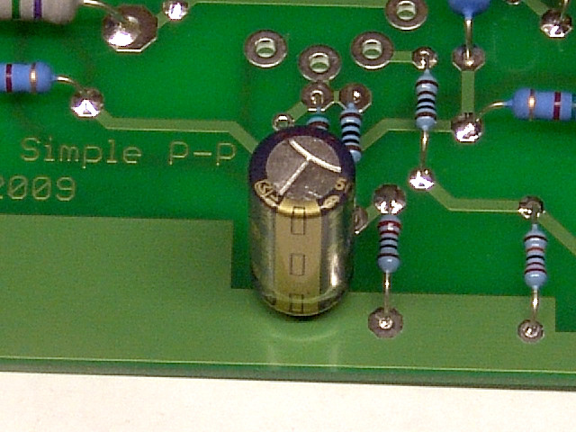 Install C200 as shown. The negative stripe should face the edge of the board.
 C201 is the feedback compensation capacitor. It is not installed at this time. The value is highly dependent on the type of output transformers that are used. The value can be determined by measurement or listening tests. It may not be needed at all in some builds.
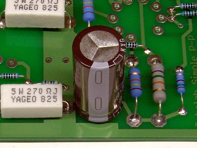 Install C202 as shown. It is polarized and must be installed in the proper direction. The negative stripe faces the edge of the board. I have used several different values for C102 and C202. The current parts list may specify a smaller part.
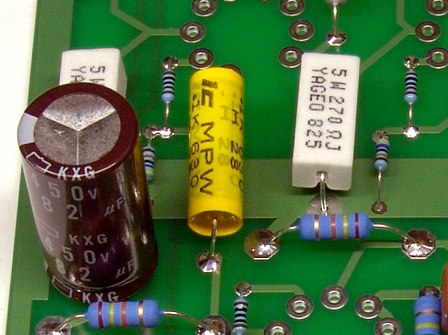 Install C203 as shown. C203 is one of four coupling capacitors.
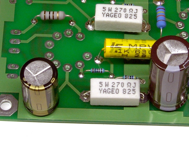 Install C204 as shown. The negative stripe should face the edge of the board.
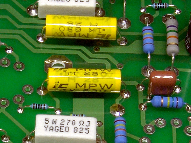 Install C205 as shown. C205 is one of four coupling capacitors.
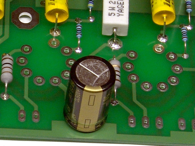 Install C206 as shown. The negative stripe should face the edge of the board.
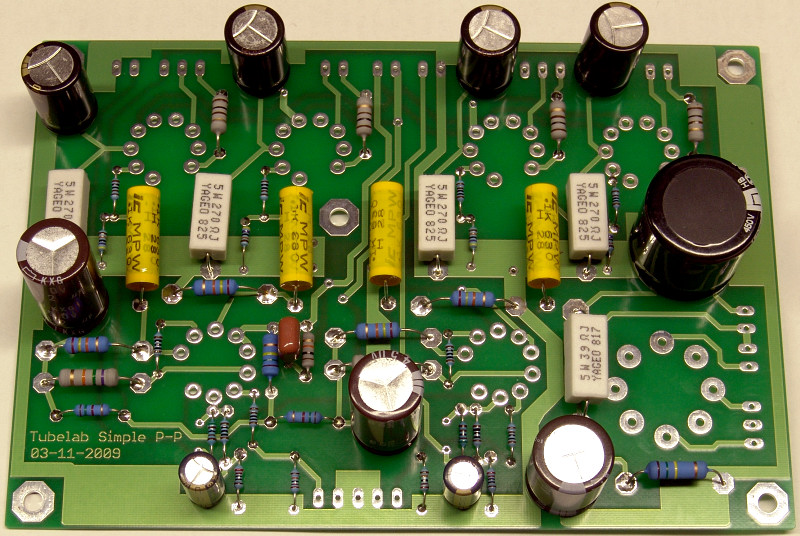 This photo shows a board with all of the capacitors in place. Your board should have all of the components in place at this time.