A brief note about photographing a project
Photographing an amplifier, or a circuit on my bench takes considerable time. Over the past two years I have refined the process to reduce this time. I used to frame and carefully expose each photo separately during the construction process, often interfering with the construction process. I now use an 8 megapixel camera on a tripod that is pre focused on a large area of the workbench. The object to be photographed is simply placed in the proper location and the photo taken. I have installed about 500 watts of overhead lighting to evenly light the work space and allow stopping down to gain depth of field. The lighting is a mix of fluorescent and incandescent to assure proper color temperature. I take a lot of pictures during the construction process, and edit them later in a photo editor. I can cut the details of a single resistor on a PC board out of a picture of a 3 foot area of the workbench. This gets the photographing process out of the way of the construction process. Even with this in place it takes twice as long to build an amplifier than it does if I am not photographing it. I built a Tubelab SSE 6V6 in a single day, this amp took a week (this one looks far better). The down side is that you don't get to see the pictures until after the amplifier is built. I often take 300 to 500 pictures during a build with varying camera settings, and object placement. I then choose the best photo after the fact. In every build until this one, it has been sufficient.
This amplifier posed several problems during the construction and in the photographing process. The other amplifiers that I built could simply be photographed while laying flat on the bench. This one is so reflective that something is almost always visible in the reflection on the amplifier surface. My reflection is visible in several of the images. This was not intentional and was not discovered until after the amplifier was completed. I went back through the 312 pictures that I shot during the construction of this amplifier. Many of the images had reflections of the overhead lighting that obscured the details that I was trying to highlight. Several contained reflections showing some details of a product that I was developing for a customer (not vacuum tube related) that must not be revealed. These can't be used here. Many contained my own reflection. I did not notice these issues during the construction and photographing of this project. The LCD on the camera can only show so much, especially under bright lights when the target image is only a fraction of the screen size. I can not un-build this amplifier to take new pictures, and there are several important details during the construction of this amplifier that can not be illustrated without these pictures.
OK, on to the amp!
I wanted a conventional amp build that didn't look too conventional. I could have just bought the typical Hammond chassis and built this amp, but I have made so many of those that I wanted something different. I chose to make my own chassis. The amp can also be built using a pre - made chassis, just skip the chassis building steps. You can use a 10 X 12 inch Hammond 1444-29 chassis for most builds. Large transformers will require a larger chassis. See the planning steps in the Fisher Cabinet Amplifier for details on planning the chassis layout and determining the size required.
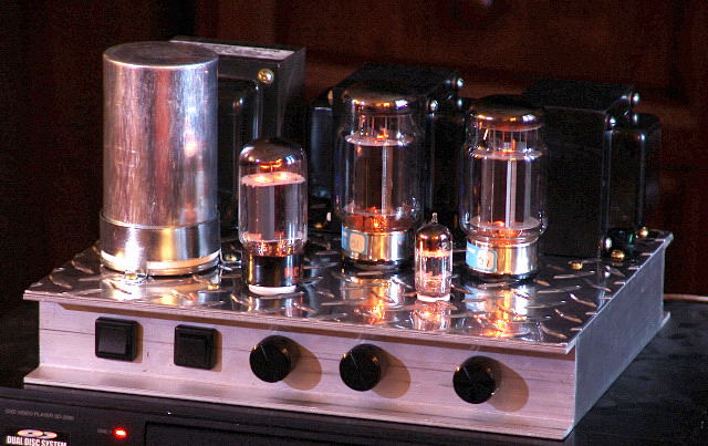 The completed amplifier (front)
I am making lettered overlays that cover the bare aluminum on the front and rear panels. These are not done yet, so they are not shown here.
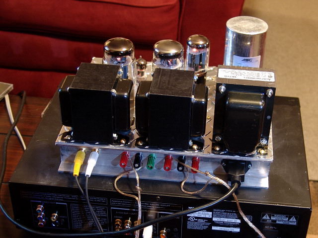 The completed amplifier (rear)
Component Choices for this Amp
The output transformers are Transcendar "300B SE transformers" obtained on Ebay ($100 to $130 per pair). They are 3K ohm impedance. I use the 4 ohm taps with the big speakers shown at the bottom of the page. This puts a 6K (nominal) load on the tubes for low distortion and about 5 watts in triode. This system is very loud and clean. I use the 8 ohm tap with my Yamaha NS-10M speakers since these "8 ohm" speakers are more like 10 to 12 ohms. These speakers are inefficient and need all of the power that they can get.
The power transformer is an Allied 6K7VG. These appear to be made by Hammond but cost less than the similar sized 274BX. I have used these transformers in HiFi and guitar amps with good results. They are $46.13 USD.
The supplemental power supply cap is an ASC 100uF 370 VAC motor RUN (not start) cap. These are cheap ($12 USD) on Ebay. This is the best $12 you can spend on your amp.
The filter choke is a Triad C-24X. These are $7.66 each. I usually use the C-14X but they are too large to hide under the chassis, and too ugly to put up top.
The output tubes are Electro Harmonix KT88EH's ($50/pair) . These can dissipate over 40 watts without issue, and sound good. The rectifier is an old RCA 5AR4. I have tried the Sino 5AR4's. They work good, but I need the fat RCA to hide a scratch on the chassis ($10). There is a front panel switch to select a solid state rectifier if desired. The driver tube is a military surplus GE 6201. Any 12AT7 type can be used ($5).
The pots are Alpha, the switches are appliance switches, selected for their single round hole mounting. These and all of the connectors are from Mouser ($15 total).
The components on the board are good quality (but not extreme) components from DigiKey or Mouser. These are the same components shown in the parts list ($25). The only thing that I would upgrade is the coupling caps.
The PC board is $35 and the chassis materials cost $30. With careful shopping it is possible to build this amplifier for $350 to $400 in materials. It will outperform amplifiers costing several times more than this in listening tests and bench measurements.
I built the amplifier that you see here for $281. How? I bought 20 of the Transcendar transformers, so I paid $90 each. I had the 5AR4 and the 12AT7's so they are not counted. I got some used EH KT88's for $10 each. Everything else was ordered from the sources listed above.
Now that I have built this amplifier, I have a few suggestions:
- Drill and cut all of the holes in the front and rear panels BEFORE gluing the chassis together. Cutting the opening for the power connector would have been much easier if the panel was not mounted yet. The recessed front and rear panels are hard to cut with restricted access to the back side of the panel. I had no problems punching the top plate, but it might have been easier to punch and drill it before assembling the chassis.
- Since I thought that this would be a simple build, I skipped the usual planning stages, and marked up the chassis using the actual components. I also decided after I finished the drilling and punching of the top plate to add 2 controls to the front panel. This was not a good idea! I found out that the new potentiometers wanted to occupy the same space as some parts on the PC board when I was mounting the components into the chassis. I was able to make everything fit by removing the input connectors from the board, soldering the wires directly to the PC board, and relocating 2 capacitors. This is not the right way to build an amplifier, and I should have not skipped the planning stages. Once you have everything planned, try to avoid making changes without careful planning.
- This chassis is a bit cramped. The channel aluminum sides take 2 inches of interior space away (not a problem with the Hammond chassis). If you are using big output transformers, you may want a larger chassis.
- Due to my crazy work schedule, and some family issues that came up, I started on this amp, and then put it aside, then started again, several times. It took over two months to finish it. Parts get lost, papers and notes get misplaced, and you forget what you did last. It would be a good idea to set aside a place and time where you can concentrate on building your amp. It will also give you less opportunity to change your mind about what you want in the middle of construction.
Making the Chassis
I got the idea for the chassis from Morgan Jones book " Building Valve Amplifiers". See the picture on page 19 and text starting on page 85. I used 1 inch (deep) by 2 inch (wide) channel aluminum and .062 (thick) polished aluminum Diamond Plate to build this chassis. The Diamond Plate is shiny and easily scratched. I found out that it is very hard to photograph with overhead lighting.
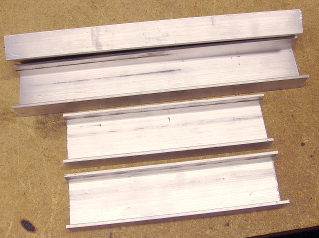
I cut 4 pieces of 1 inch by 2 inch aluminum channel. 2 pieces are 8 inches long, and 2 pieces are 10 inches long. I used a table saw with a 10 inch cutoff wheel, but a jig saw, band saw , or even a hacksaw could be used depending on your patience and skill level. The holes in the front and rear panels (long pieces) should have been drilled (or cut) next.
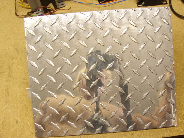
Then I cut a 10 inch by 12 inch piece of polished aluminum diamond plate. It is .062 inch thick. I ordered the diamond plate and the channel aluminum over the internet. I cut my piece from a 12 X 48 panel using a Dremel tool and a cutoff wheel. It took forever but came out nice. I would have used the table saw but it was raining outside.
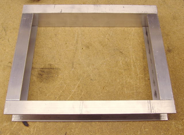
I test fit the pieces together. I will then glue them instead of using screws to limit the number of screw heads on the top plate of the amp. The diamond plate sits on top of this, but is not shown here.
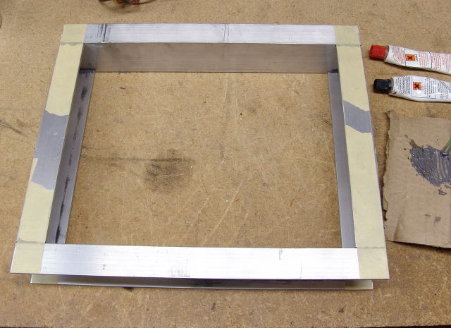
I then glued the pieces together using J-B weld, a 2 part epoxy that works good on aluminum. Everything was taped to keep it from moving while the epoxy cures.
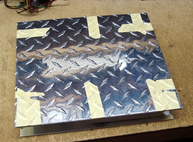 Next I glued on the diamond plate. And taped it in place until the epoxy cures.
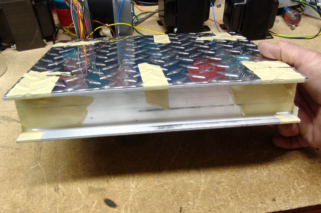 Front view. The switches and volume knob will be inside the channel.
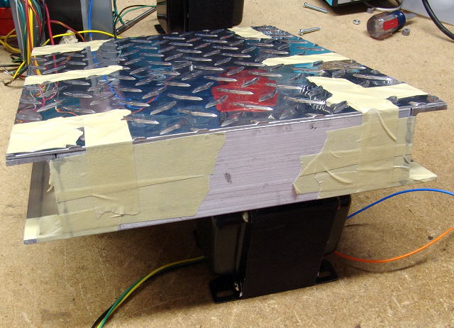 Side view.
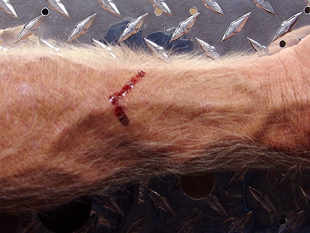 Warning, Freshly cut, punched, or drilled metal is sharp and even incidental contact will make you bleed!
Using Your Chassis to Make an Amplifier
In my previous amplifier builds I used a drawing program, or paper and pencil to plan the component layout of the chassis. If you have limited experience building amplifiers, I would highly recommend doing this. See the other amplifier designs on this web site for details. This amplifier has only 5 major components requiring mounting to the chassis (3 transformers, the PC board, and the big cap), so I got lazy and just used the components (or the paper copy of the PC board) themselves to mark the chassis.
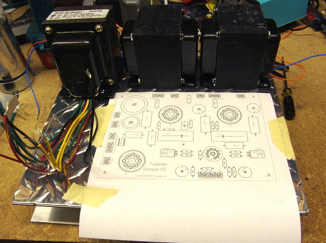
This photo shows the three transformers placed in their proper positions along the rear of the chassis. Make sure that there are no obstructions where the holes will be drilled. You also need to mark the holes for the transformers wires. The paper print out from the PC board is taped it place. Remember that the PC board will be mounted under the chassis. I also test fit the big motor RUN cap, but it is not shown here. I marked its holes with the power transformer turned around so that its wires were not in the way.
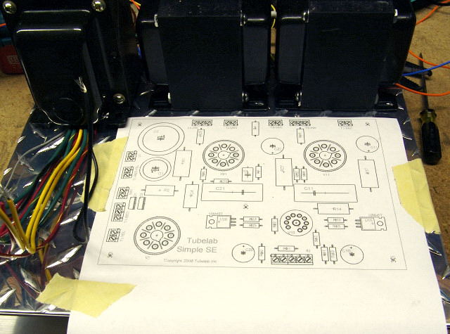 A closer view.
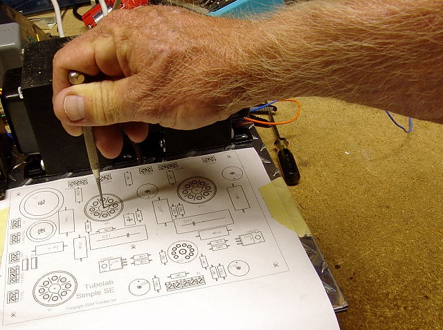
I used a scribe and a small hammer to mark the center of each hole. I have the proper tool (center punch) for doing this, but it wandered out of my tool box, and could not be found.
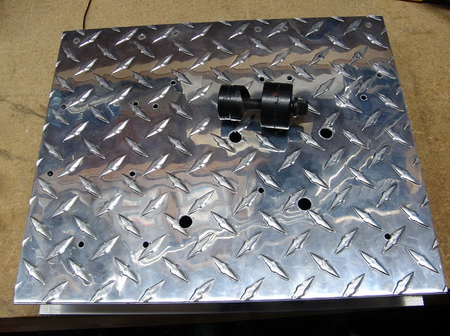
Once you are sure everything is properly marked, drill all of the holes. I used 1/8 inch holes for all of the screws, and 3/8 inch holes for the chassis punch (shown) that will be used to punch the large holes for the tube sockets. I used a 1/2 inch drill bit by hand to clean the sharp edges off of the small holes. The large holes will be taken out by the punch, so I didn't bother with them. The holes for the transformer wires are not drilled yet. They are made with a 1/2 inch drill bit.
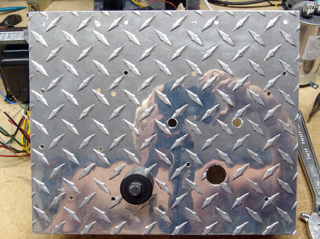
Next, I used two different size chassis punches to make the holes for the tubes. I used a cheap (Harbor Freight) punch set to make the small hole for the 9 pin tube. This is called a 1/2 inch pipe (or conduit knockout) punch, but makes a 0.89 inch hole. Ordinarily this would be too big for a 9 pin socket, but I used a larger than normal socket, and it is mounted to the PC board, not the chassis. I used a standard Greenlee octal (1.12 inch) chassis punch for the octal socket holes. I learned the hard way that you want the die (shown) on the bottom, and the punch (see picture below) on the top side of the chassis.
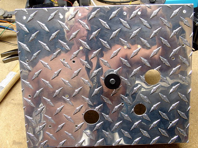
Here 3 of the holes are done, and the fourth is started. Here the punch is on the top side of the chassis, and the die is on the bottom. This puts the wrench on the bottom of the chassis, which could be a problem on deep chassis. Look carefully at the hole punched with the die on the top. You can see the mark that it made just below the hole. I will have to use a fat rectifier tube to hide it if it won't polish out.
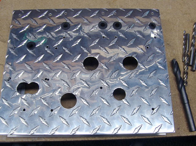
Here is the chassis with the top plate punched and drilled. I marked the holes for the capacitor, neglecting to account for the rolled edge (lip) in the can, so I had to double drill two of the holes. Fortunately this will be covered up by the mounting clamp. I made the figure eight holes for the capacitor pins by making two punches with the 1/2 inch pipe punch.
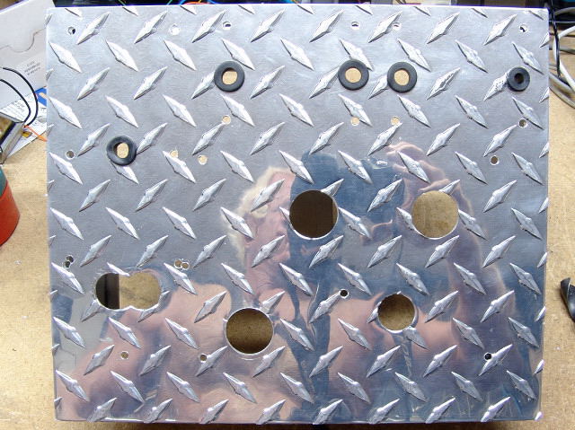
Grommets are placed in the holes that the transformer wires pass through. This is important to avoid sparks later.
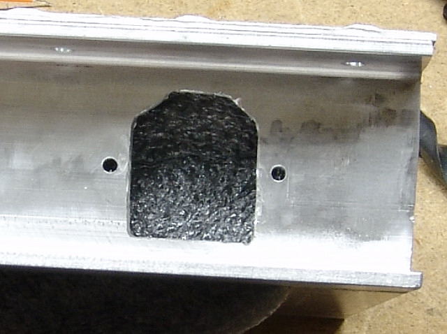
I used a Dremel tool with a cutoff wheel to cut the opening for the power cord receptacle. It would have been much easier to do this before mounting the rear panel to the chassis plate. The foam is in place just for the photo. Without it the camera focuses on the front panel.
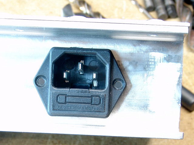 Here I test fitted the power jack in the hole. I then removed it so it would not be contaminated with aluminum dust.
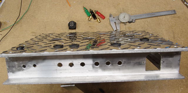
Next I drilled all of the holes for the rear panel connectors. On the left there are the two input jacks. In the center is the speaker connectors. There are 3 banana jacks for each channel since I am using the 4 ohm and the 8 ohm connections.
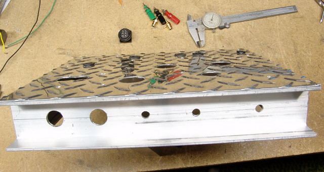
This is the drilled front panel. The two large holes on the left are for the power and rectifier switches. In the center are two controls for options that are still in development. The volume control is on the right. The chassis is now complete and ready for assembly.
Here is where the trouble started. I didn't carefully plan the component layout when I marked out the chassis. Then, after a month of inactivity (I wasn't home to work on the amp), I decided to add two controls for experimental circuits. Unfortunately, I didn't realize that they would occupy the same space as some of the components on the PC board. Fortunately I could move these parts out of the way. In my frustration I took no photos during the mounting of the components.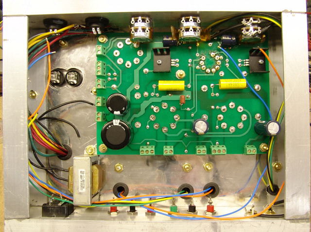
Here all of the components are mounted. The PC board is mounted using spacers. I found some Nylon spacers that put the tube sockets flush with the top of the chassis. The two capacitors that were standing up right where the two pots are, have been laid down on their sides. I used brass hardware for mounting everything. I couldn't decide between brass or stainless steel, but the home improvement center did not have stainless, so my choice was made for me.
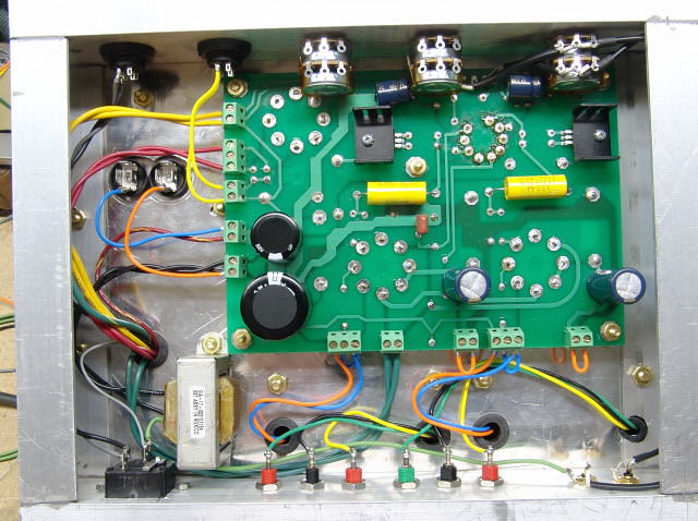
I connected up all of the wiring. The transformers I used do not have ultralinear taps, so I jumpered the amp into triode mode (blue jumpers). I also placed jumpers (orange) disabling the cathode feedback, since I don't need it in triode mode. I connected front panel switches in place of these jumpers on other amplifiers. I did not add a standby switch in this amplifier due to the lack of front panel space.
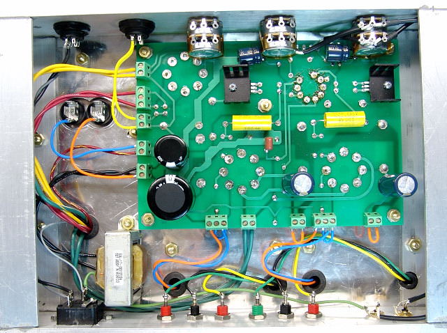
Another picture. I installed a 2 amp fuse, flipped the amp over, and fired it up. It instantly came to life and worked great. After some listening I have decided to upgrade the coupling caps, but I must wait for the AuriCaps to arrive.
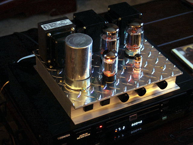
Here the amp sits on top of the DVD player that I use for CD's. I have been too busy listening to finish the front panel. I have not yet added the mesh cover over the bottom of the amp or the rubber feet. The feet are needed to allow air movement under the amp, and the mesh cover keep fingers away from the high voltage!
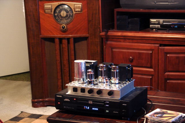
Listening tests. The old radio in the background is the left channel speaker cabinet. There is an identical radio on the right of the TV. This amp does not fit in with Sherri's decorating scheme, so this is just temporary testing. The Fisher Cabinet Amplifier is being built to live behind the door on the left of the TV stand. It is also a Tubelab SSE with identical circuitry, but uses Hammond OPT's and switchable UL operation for truly wall shaking bass with these speakers.