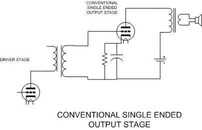
The single ended output stage has been with us since the beginning of the vacuum tube era. It still enjoys good success today. There are a few drawbacks, however. Because all of the DC current drawn by the output tube flows through the output transformer, the transformer must be designed to accept this current without core saturation. A well designed transformer will use this bias current to avoid the hysteresis problem found in push pull amplifiers. This is why an SE amplifier usually exhibits greater musical detail. The output transformer must have an air gap in its magnetic circuit to avoid saturation, which reduces the inductance. To compensate for the loss of inductance larger iron and more primary turns are added making the transformer large and expensive. The solid state output transformer avoids the saturation and hysteresis issues in a unique manner.
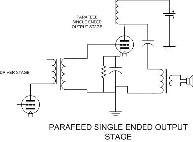
There have been several amplifiers designed to avoid this problem. The most common is an output topology known as parafeed. The parafeed (parallel feed) design solves the problem of DC current in the output transformer but has its own issues. Now there are two large inductances (in parallel, which reduces the total inductance) and a capacitor associated with the output stage. Careful design of the magnetic devices is required to avoid frequency response problems. This is why both are usually sold together. This is usually just as large and expensive as a good SE output transformer.
Are there any other ways to accomplish the same thing? Sure. In a simple R-C coupled voltage amplifier the choke is replaced with a resistor. This works well, and common practice for small signal amplifiers. Can we build a bigger one? Yes, within reason. The resistor must be large, because it will dissipate a lot of power, and the efficiency is poor. I built an RC coupled output stage (on Tubelab 1) using a 6B4. It took over 500 Volts of B+ to get 2 Watts of power, but it sounded nice.
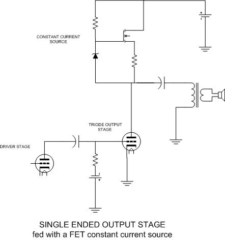
If you dig deeply into vacuum theory you will find that the ideal load for a triode is an infinite impedance. This applies to both the DC load and the AC load. Can we accomplish this? No, because no power can be developed across an infinite impedance. We can try to improve the situation however. We can feed the triode with a constant current source instead of a large inductor as in the parafeed design. This will solve the DC load issue. This does not come without a price. Since the transformer has a low DC resistance the B+ needs to be only a few volts higher than the desired plate voltage. With a current source feed, the B+ requirement approaches twice the desired plate voltage. If you look at the plate curves of various devices you will see that a pentode or a mosfet make good current sources. Triodes do not. Also note the use of fixed bias. I am not sure why but both of these circuits behave strangely when tried with cathode bias. (limited experimentation, may work with different tubes)
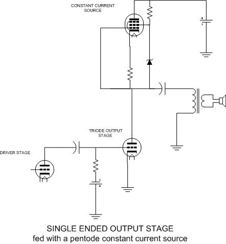
Both of these circuits go a long way toward increasing the DC resistance that the triode sees, but how do we increase the AC load impedance that the triode sees? If this were a small signal amplifier the traditional answer would be to use a cathode follower circuit between the triode and the load. It turns out that the pentode can do double duty as a constant current source and a cathode follower just by moving one part. Change the triode over to cathode bias and this circuit starts to look familiar. We have used this circuit with a triode for the top tube in several low level circuits, it is known as the SRPP circuit.
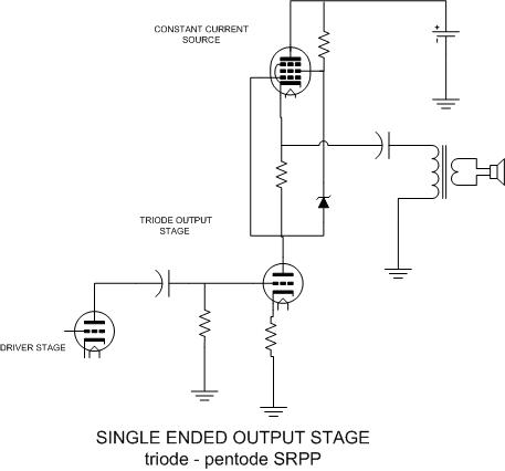
Can we use a triode? Yes, but a pentode makes a better current source and a better cathode follower than a triode. As a note, I did try an SRPP output stage with a 6AS7 tube and it was highly unstable. This tube is known to be prone to runaway however.
Single ended triode amplifiers are prone to another issue. If you crank up the drive level in search of more power the grid of the output tube will be driven positive and will start to draw current. I was taught (many old textbooks agree) that you should avoid this. (true on most tubes) Many directly heated triodes are quite linear when the grid is driven positive. Many transmitting triodes are designed for operation in this manner. So what is the problem? When the grid is negative it is a high impedance, when the grid goes positive it becomes a low impedance. There is a large abrupt change in grid impedance when the grid transitions into the positive region. If your driver stage is not designed for this it will distort badly.
How do we solve this problem. It turns out that there are a few triodes (called zero bias triodes or class B triodes) like the 811A, 838, 3-500Z and others that can be operated with positive grid bias at reduced plate voltage. Since most of these tubes were made for very high plate voltage, they need positive grid bias at "normal" voltages. An 811A with 500 volts on the plate will draw 80 mA with +20 volts of grid bias. Since it only needs a few volts of drive the grid is always positive and the transition never happens. The driver tube must be capable of driving a low impedance. Everyone seems to need a name for their unique tube circuit, so we call this A3 operation since grid current is drawn for 360 degrees. This only works with tubes designed for this type of operation.
There is another way to solve the grid transition issue. Grounded grid operation solves the problem a different way. If the grid is grounded and the drive applied through the cathode, the input impedance remains low all of the time.
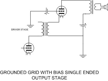
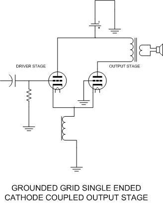
This circuit works well with any type of triode.