Table of Contents
- Getting Started
- Resistors
- Tube Sockets
- Capacitors
- Semiconductors
Connectors
- Wiring Diagrams
- Checkout
- Enclosures
Connectors
This board uses connectors for all off board wiring. This allows the transformers and all other wiring to be done without soldering. This was a highly requested feature since I asked for comments and improvements on the Tubelab SE board. Some purists may not want connectors in the audio path (especially at the input). If this applies to you, you may solder wires directly to the PC board. Keep in mind that soldering wires (especially heavy transformer wires) directly to the board has been the greatest cause of ruined boards. I have used these connectors on every board that I have built with no issues. It makes board testing much easier, and doesn't affect the sound.
As with the other large parts the connectors can be mounted on either side of the PC board. There are two sets of instructions, so choose the ones that apply to your particular amp design. In this case the steps are the same on either side of the board, only the pictures change.
Installing the Connectors (top side assembly)
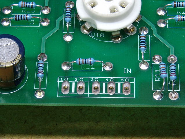 The input connectors go here. There are 5 holes. I have used two 2 pin connectors here, leaving the center hole unused. The center 3 holes are all GROUND, so an extra hole is available. If you need the extra GROUND connection, substitute a 3 pin connector for one of these connectors.
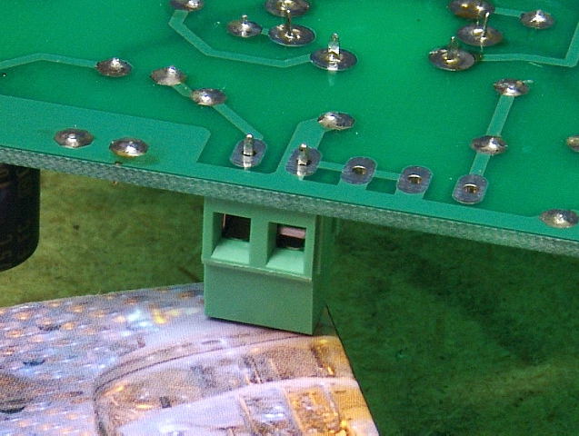 Place a 2 pin connector in the right most (from the top) two holes. Make sure that the holes for inserting the wire are facing out (away from the board), Flip the board over and rest it on a book to keep the connector from falling out. Solder it in place.
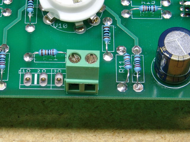 It should look like this when done.
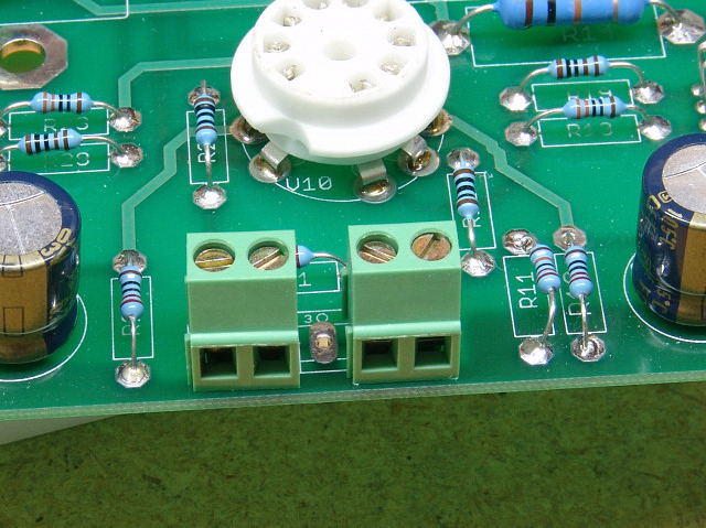 Install another 2 pin connector on the left side of the input area. The center GROUND pin is left unused in this example. A 3 pin connector can be used in one of these places if the additional GROUND pin is needed.
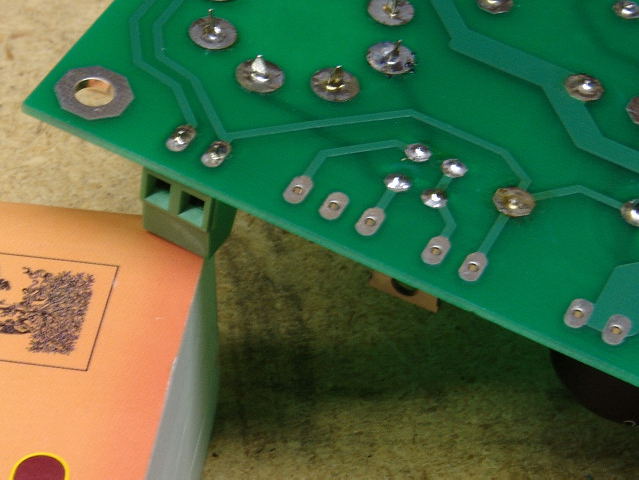 Install a 2 pin connector in the T1-YEL position.
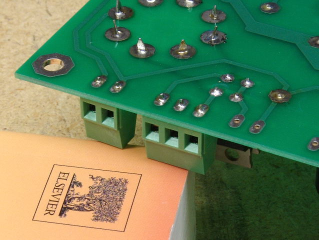 Install a 3 pin connector in the T1-RED position. There is nothing connected to the center pin. Do not use it for any connections. This is needed to assure adequate spacing for the voltages seen on these pins.
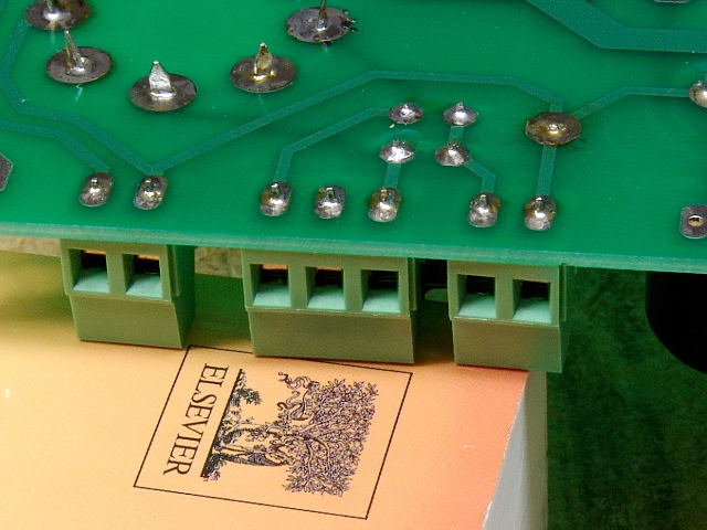 Install a 2 pin connector in the SW1 position.
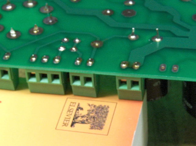 Install a 2 pin connector in the T1-RED-YEL position.
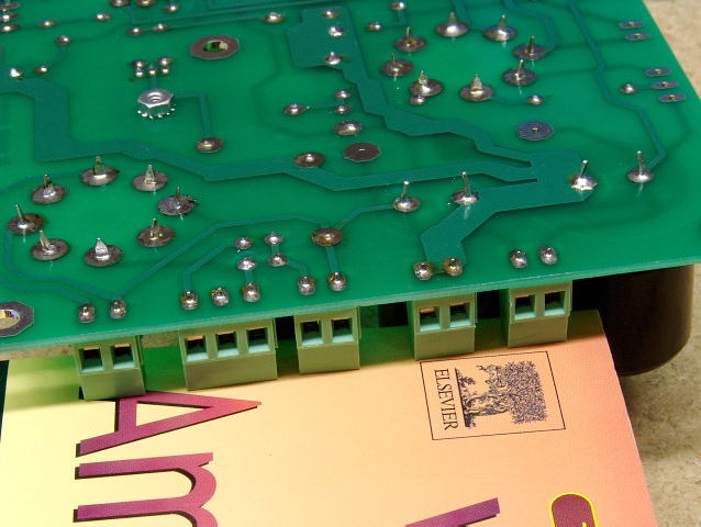 Install a 2 pin connector in the L1 position.
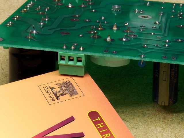 Install a 3 pin connector in the T3-PRI position.
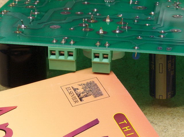 Install a 2 pin connector in the T1-GRN position.
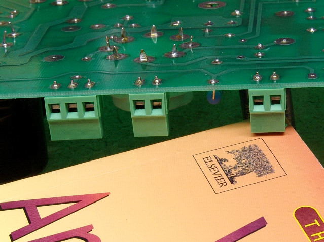 Install a 2 pin connector in the T3-SEC position.
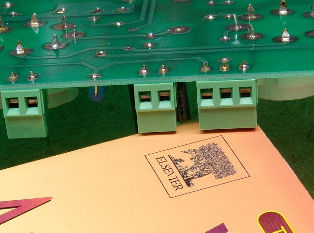 Install a 3 pin connector in the T2-PRI position.
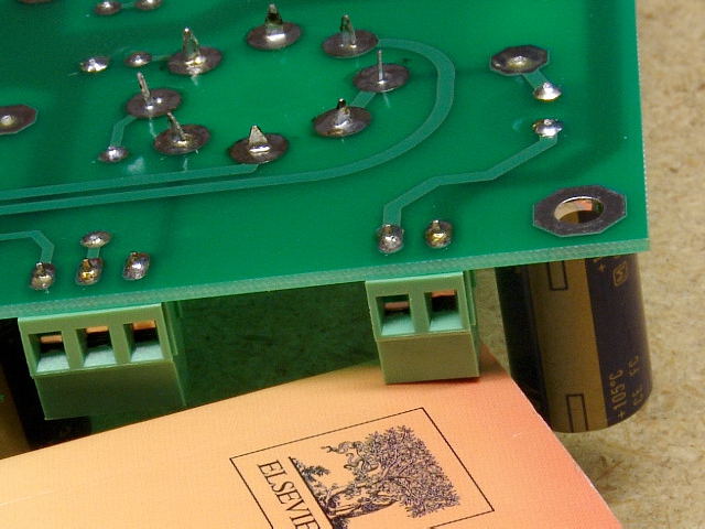 Install a 2 pin connector in the T2-SEC position.
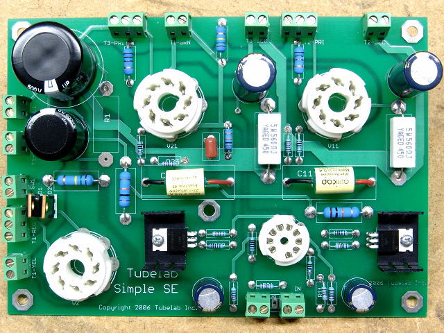 Your board is now complete!
Installing the Connectors (bottom side assembly)
 The input connectors go here. There are 5 holes. I have used two 2 pin connectors here, leaving the center hole unused. The center 3 holes are all GROUND, so an extra hole is available. If you need the extra GROUND connection, substitute a 3 pin connector for one of these connectors.
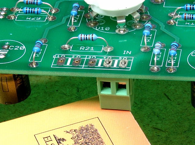 Place a 2 pin connector in the right most (from the top) two holes. Make sure that the holes for inserting the wire are facing out (away from the board), Flip the board over and rest it on a book to keep the connector from falling out. Solder it in place.
 Solder the right side input connector, and install another one for the left side.
 Install a 2 pin connector in the T1-YEL position.
 Install a 3 pin connector in the T1-RED position. There is nothing connected to the center pin. Do not use it for any connections. This is needed to assure adequate spacing for the voltages seen on these pins.
 Install a 2 pin connector in the SW1 position.
 Install a 2 pin connector in the T1-RED-YEL position.
 Install a 2 pin connector in the L1 position.
 Install a 3 pin connector in the T3-PRI position.
 Install a 2 pin connector in the T1-GRN position.
 Install a 2 pin connector in the T3-SEC position.
 Install a 3 pin connector in the T2-PRI position.
 Install a 2 pin connector in the T2-SEC position.
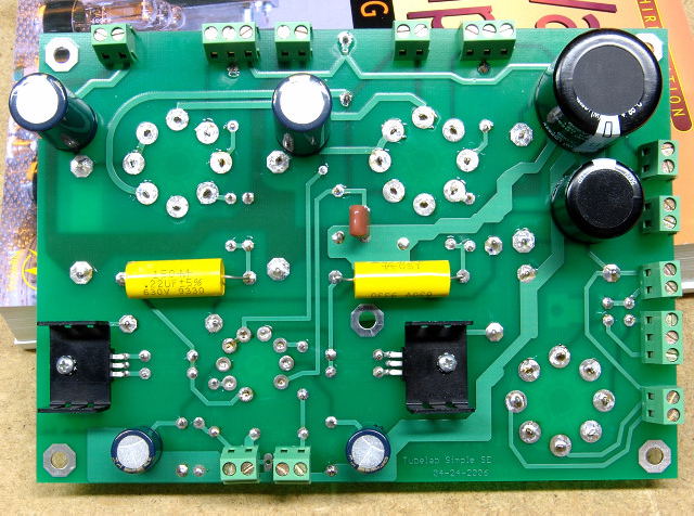 Your board is finished.