Table of Contents
- Getting Started
- Resistors
Tube Sockets
- Capacitors
- Semiconductors
- Connectors
- Wiring Diagrams
- Checkout
- Enclosures
Tube Sockets
Next you will be installing the tube sockets. It is absolutely imperative that you be sure that they are oriented correctly before soldering. It is almost impossible to remove a tube socket without damaging the board or the socket.
The sockets are installed from the top of the board and soldered from the bottom. Care must be exercised to avoid applying too much solder, since it will flow down the pins on the socket and into the socket itself. In extreme cases solder will actually fill up the socket, making it impossible to insert a tube. Check your first few pins from the top before soldering them all. If you don't use enough solder the joint may fracture when you are changing tubes.
A common old trick is to insert an old tube into the socket before soldering. This is usually done to insure pin alignment. I don't recommend this because it is too easy to solder the tube into the socket. The octal and many 9 pin tubes are made with solder on the pins. Too much heat, it will melt, and the tube is permanently soldered into the socket. I have done this and there is no way to get it out!
Some of the pictures showing HOW to insert and solder the tube socket into the PC board show a Tubelab SE board. These pictures are used to illustrate the technique, The instructions are specific to the SSE board.
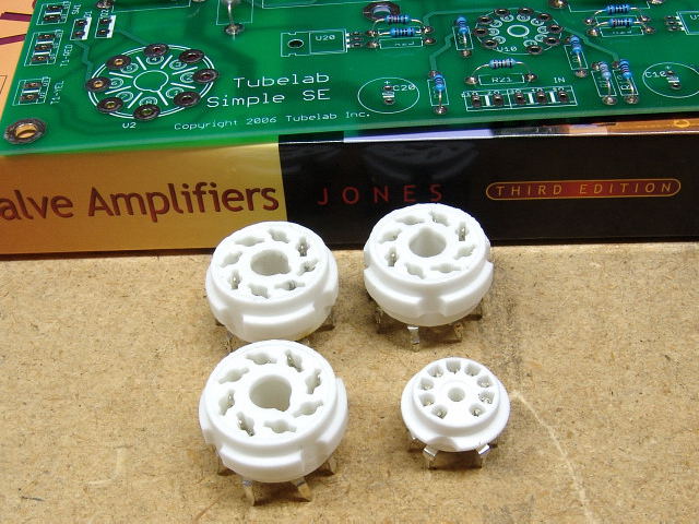 You will install three octal sockets and one 9 pin miniature socket in this board. Start with the octal sockets.
Octal Socket Installation
TIP: You can insert all 3 octal sockets, then place the board face down on a flat surface before soldering. Solder all 3 sockets at the same time. This will ensure that they are all in the same plane. Place all 3 sockets in the board, verify that they are aligned correctly, place a flat surface (hard book or another PC board) on top of the board, then flip the whole sandwich over. Then solder all 3 sockets.
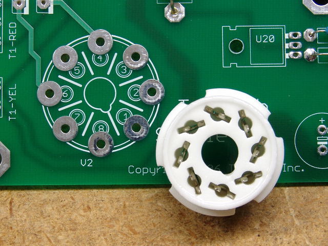 You will install three octal sockets in the SSE board V2, V11, and V21. Note that the board is clearly marked as to the orientation of these sockets, however the socket will fit into the board in any orientation. Be sure that the socket is oriented correctly before soldering.
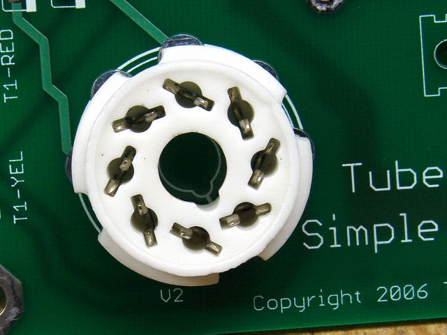 Insuring that the guide pin notch on the socket lines up with the silkscreen printed on the board, insert the socket into the board. Some manipulation of the individual pins may be needed.
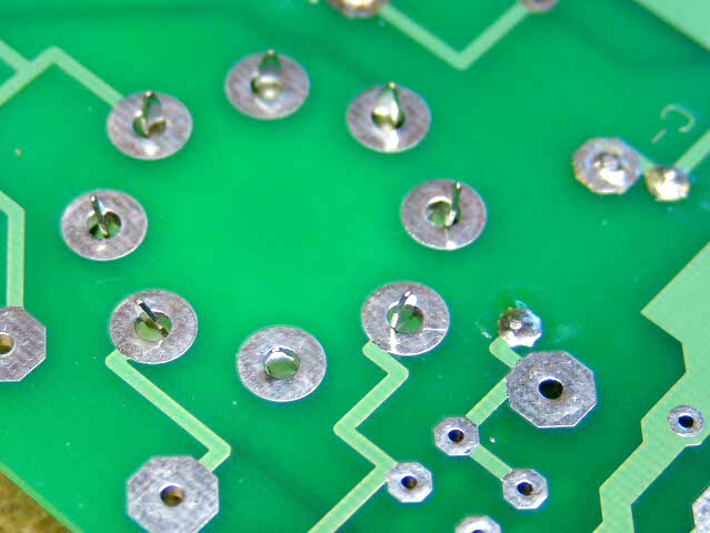 While holding the socket and the board, carefully flip the assembly over onto the work area. Place a small object under the other end of the board so that the board is level and the socket sits flush against the board. I don't recommend bending the pins to hold the socket in. This makes it almost impossible to remove the socket if it ever needs replacement.
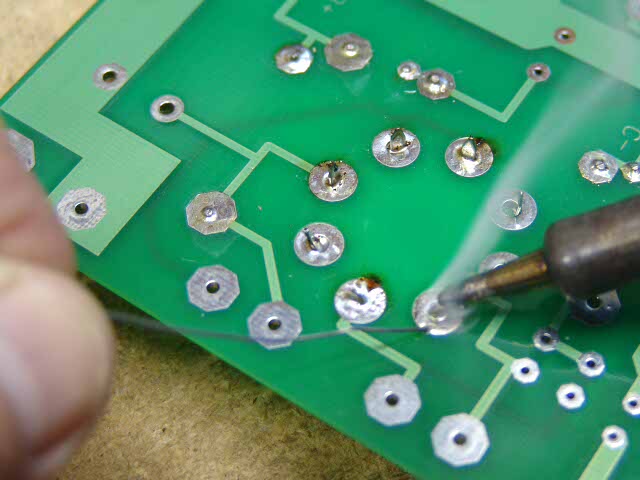 Carefully solder the socket in place, one pin at a time. If you have never done this before, flip the board over after soldering each pin and make sure that excess solder did not run down the pin into the socket. This is unlikely with the octal socket, but it is good to check.
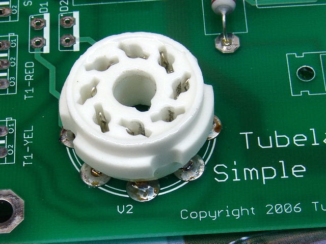 The soldered socket should look like this (top).
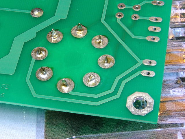 The soldered socket should look like this (bottom).
 Insert, and solder an octal socket for V2.
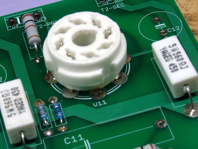 Insert, and solder an octal socket for V11.
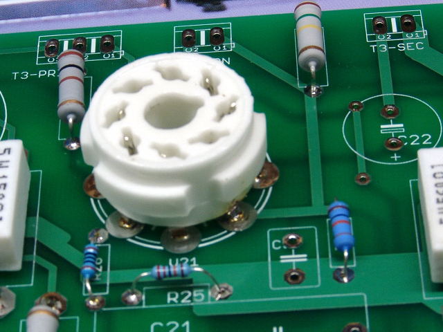 Insert, and solder an octal socket for V21.
9 Pin Socket Installation
There is one 9 pin miniature tube socket used in this board, however there are two ways to install it.
The socket can be installed flush with the board like the other sockets. This is the normal method for installing the 9 pin sockets, and would be used where all of the components are mounted on the top side of the board, and the board is mounted in an enclosure such that there is unrestricted access above the board. This construction technique is referred to as top side assembly.
The socket can also be mounted spaced slightly above the board. This would be used in situations where some of the components are mounted on the back side of the board, and the board is mounted just below the surface of the chassis. This allows the appearance of a traditional amplifier chassis, however this is not as strong as flush mounting so it should only used if you are mounting the board in this manner. This is referred to as bottom side or inverted assembly.
Read the installation procedure for both methods, and then decide which is right for you. If you are not certain, read the Enclosure Options page and the Mounting page.
Flush to the Board Mounting
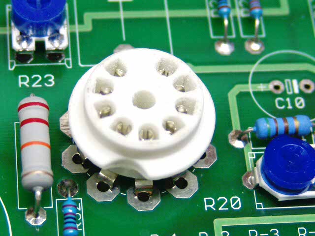 Insert the socket into the board. Some manipulation of the individual pins may be needed. These will only fit into the board one way. The socket is pressed fully into the board such that the pins will not go any further. The photo above shows this. (Tubelab SE board shown)
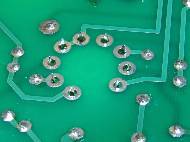 The bottom of the board should look like this before soldering. The socket is resting on the books to keep it flush with the board.
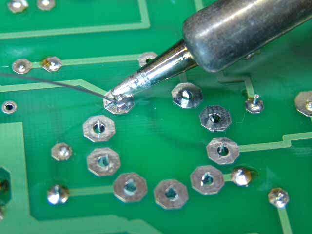 If the socket is flush to the board, and straight, solder it in place. Check each pin for excess solder on the top side of the board.
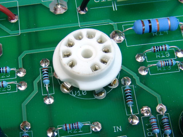 The completed socket should look like this.
Spaced Above the Board Mounting
In some situations it may be desirable to space the socket off of the board a bit. Since the 9 pin socket is shorter than the octal sockets, it needs to be elevated slightly if the board is being mounted directly to the underside of a chassis. This allows the bases of all tubes to be at a similar height. This technique is used when some other components are mounted on the back of the board (inverted assembly). It must be stressed that the tube sockets must be on the top side of the PC board.
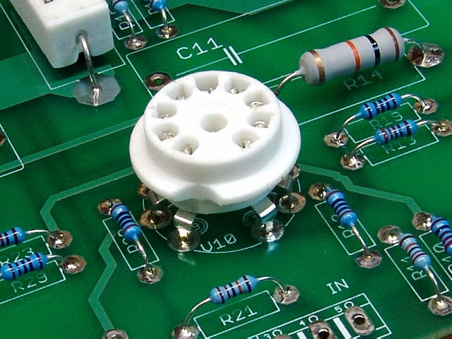 Here the 9 pin socket has been spaced above the board slightly.
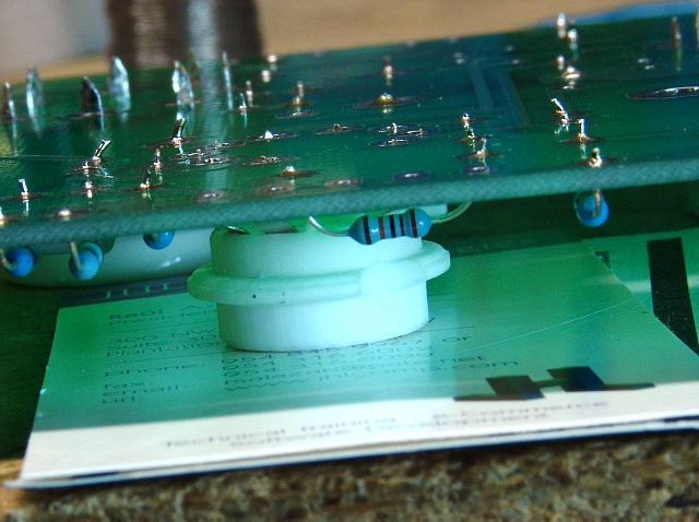 To accomplish this, the 9 pin socket is inserted into the board, and the board is placed face down on the work surface. I placed two business cards under the socket to raise it up enough for the pins to be completely through the PC board. The tip of each pin can be seen just above the surface of the board. This allows the largest possible contact area between the pins and the board.
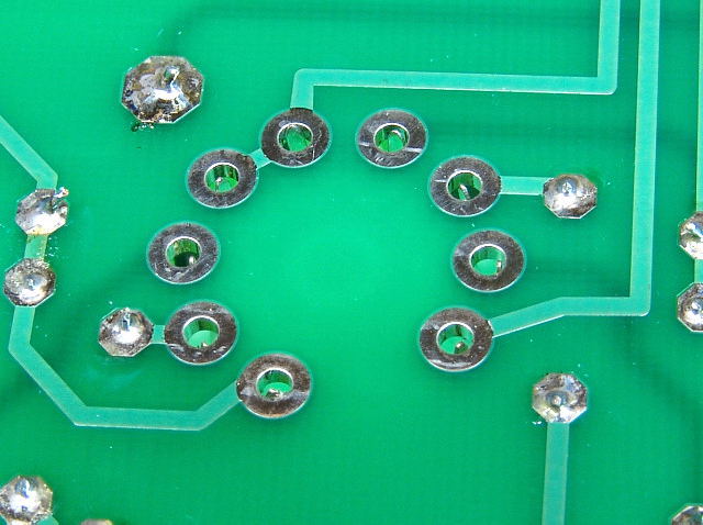 Here is another view of the pins before soldering. Solder the pins applying enough solder to fully fill the hole allowing solder to completely enclose each pin.
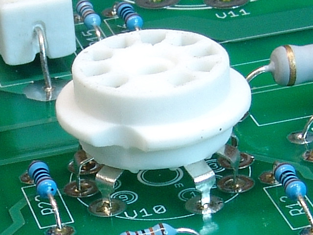 The socket should look like this when done.
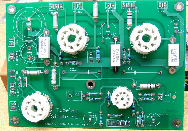 Your board should look like this at this point. If it does proceed to the Capacitors page.