Assembly Manual • Schematic • Parts List • Tubes and Applications • Design • Simulations
The Output Stage
The SE amp cad program from TubeCad was a great help in the initial design stages of this amplifier. By trying out several different sets of operating conditions in the computer I could eliminate hundreds of possibilities without playing with electricity. How do you find a set of operating conditions that will work with 3 different tube families? Well, I ran 3 different instances of TubeCad simultaneously. One was simulating the EL-34 amplifier (shown below) while another was simulating the 6L6 amplifier, and the third was crunching on the KT-88 amp. I tried each set of conditions on each simulation, and pushed the values around until I found a set that worked with all 3 tube types. Doing this with real amplifiers would take forever.
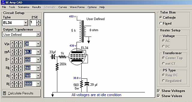
The first screen in TubeCad shows the schematic of the output stage. At the right you set up choice of fixed or cathode bias. The other conditions are for DHT's. At the upper left you choose the tube type, and the number of tubes in parallel. Below that you choose from a list of popular output transformers, or choose "user defined" and input the parameters. Below that are the sliders that let you play with the parameters. Vin is the AC drive level in peak AC volts. Next is the tube current. Below that is the B+ voltage, followed by the cathode resistor. The next two are the DC resistance of the output transformer, followed by the impedance. When you adjust these you see the voltages change on the schematic. Some of these interact. You can change the tube current, and the cathode resistor will change, or change the cathode resistor and the tube current will change. In my case I wanted the same cathode resistor in each case, so I set this and then watched the current. The screen shown below is where the action is.
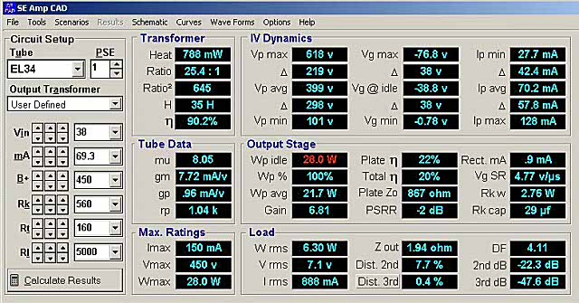
Here you see the results of your simulations in real time. The same sliders are on this page. As you move one, the results change instantly. You can set up Tubecad to see this page and the schematic page at the same time. I could not fit three of these pages on my screen at the same time though.
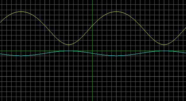
There is a "virtual oscilloscope" feature that lets you "see" the grid (blue) and plate (yellow) voltages. The "scope" can be set on DC or AC coupling. The volts per division can be adjusted also. The Frequency of the drive voltage can be adjusted. A sine triangle or square wave can be used. This is very useful to figure out where clipping is coming from.
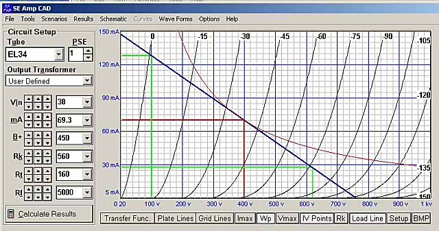
Above is the load line plot. Again this happens in real time. Move a slider and the graph is instantly redrawn. The red lines are the actual operating points seen by the tube. In this case the tube gets 399 volts and 69.3 mA. The green lines show the extremes seen by the tube at the signal minimum and maximums. The dark blue line is the "load line". The slope of this line represents the load impedance. Move the RL slider and it tilts in real time. The curved red line is the maximum dissipation. All of the above mentioned lines should be below this curve, or your output tube may be glowing red!
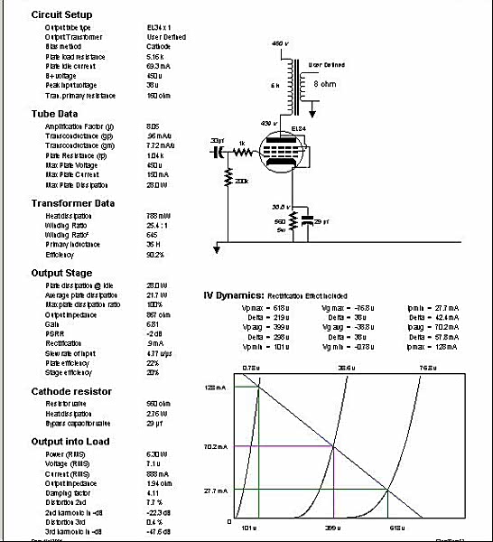
SE amp cad will print out a summary page with all of the important data on it. One for the EL-34 case is below ( I accidentally cut the header off trying to get a legible picture) :
As mentioned before, there are limitations. TubeCad assumes triode strapped operation for all of the pentode tubes. There is a fixed list of tubes. All of the popular tubes are included. I used TubeCad extensively when designing the 845SE. It modeled A2 operation accurately. I don't know if it is possible to add a tube to the list. There is a fixed list of output transformers, they are all expensive transformers. The thought is that this allows you to optimize the amplifier CIRCUIT not the transformer. I just use the user defined parameters. TubeCad does not handle any type of local feedback. Even if it did, cathode feedback would not be accurate without an extensive model of the output transformer. Given these limitations, and the low price, I find it very useful during the initial design phase of an amplifier. It is also useful for " how much power can I squeeze out of a given tube" and " how much B+ voltage will I need" scenarios. I ran these simulations for 4 popular output tubes. The results are on the tubes and applications page. See this page if you are not building one of the standard configurations. More TubeCad simulations are shown of the PowerDrive cookbook page.
The Driver Stage
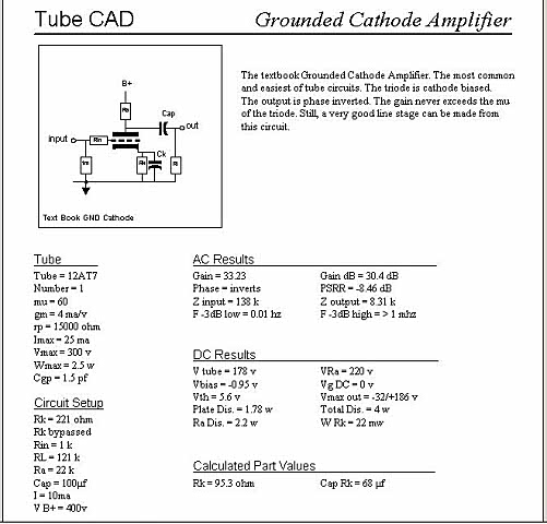
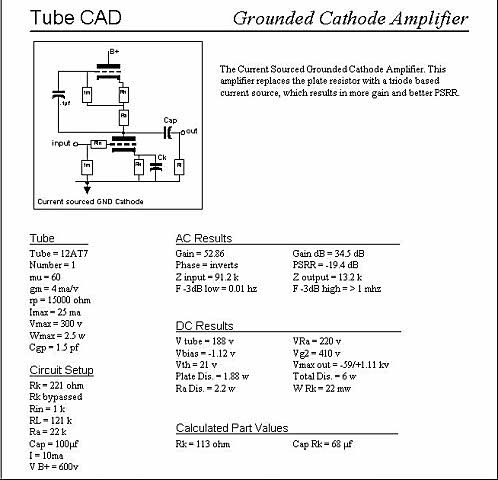
I used the original Tube Cad simulator to figure out a few things before I could build the driver stage. At first I set up a simulation with a simple grounded cathode amplifier stage that used a resistive load. I went through every tube in the Tube Cad library trying to get a voltage gain of 50 and a tube current of close to 10 mA. The 12AT7 amplifier below is the best that I could do. At the same time I had a few voltage amplifiers breadboarded on the Tubelab system for testing. The results matched the simulations.
I could get the required gain from a 12AX7. The 12AX7 has a Mu of 100. In order to get a voltage gain of 50 I had to use a load resistor of 150K and a B+ voltage of 450 volts. This means a maximum tube current of 2 mA in order to get enough output voltage. The output impedance was 85 K ohms, almost half of my gain would disappear when the load was connected. If I used a tube with a resistive load I would need a Mu of at least 100, probably more. How do I know this? I used the Tube Cad simulator.
In an attempt to find out if my expectations were realistic, I created my own mythical tube in the simulator (I called it the 12ZZZ7) and gave it all of the qualities I would want. I then simulated a RC coupled amplifier and adjusted the Mu to get the voltage gain of 50 with 10 mA of plate current. I needed a Mu of 105.
The Tube Cad program has a circuit that uses a triode based "pseudo CCS" as the plate load for the amplifier tube. I simulated this circuit and found that it could give the required gain and almost the required output impedance. I built one using an IXYS CCS IC and it worked very well.
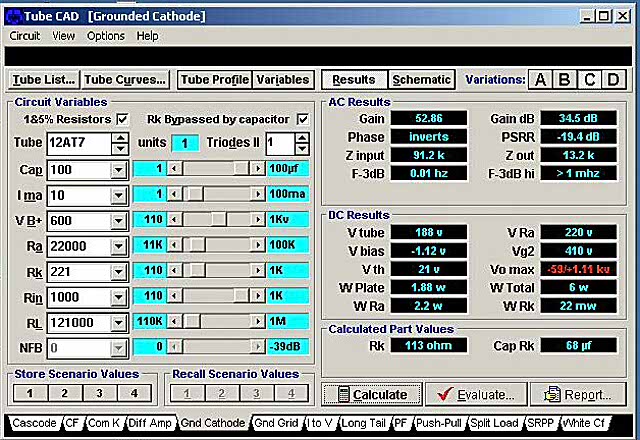
The circuit summary is shown below.
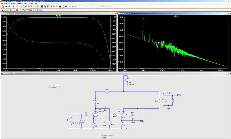
I also modeled the entire amplifier in LT spice. This is a freeware spice simulator downloadable from Linear Technology, the IC company. Vacuum tube models can be found on the internet. These came from Duncan Amps. I did this simulation in order to have a known starting point for developing some of my newest vacuum tube and hybrid circuitry.
