The SIMPLE P-P Assembly manual
There have been several requests for a drill template to mark the chassis. Here is a PDF of the PC board silkscreen layer. It can be printed and used as a drill template. Make sure that your printer output is 1 to 1 before drilling (lay the board on the paper and compare).
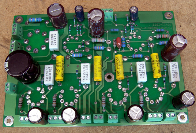
A freshly built Simple P-P Board
Thank you for purchasing our board. Please read this page carefully and understand it before soldering any parts on the board. Please look over the complete assembly instructions, including the initial Checkout and Setup instructions before starting assembly. If you don't feel that the kit is within your capabilities, you may return it for a full refund (less shipping) BEFORE any assembly is started. We can not accept returns on assembled, or partially assembled kits. We can not accept returns on any kit where any components (including the PC board) have been modified or defaced in any way such that it can not be resold as new.
The Simple P-P board was designed from the ground up as an easy to build amplifier kit, without compromising performance. After offering the Simple SE, I received a lot of requests for a P-P amp with the same easy to build design.
Many people asked for an amplifier that didn't use expensive tubes or unique parts. People wanted an amplifier that was easy to build. They wanted an PC board that could accommodate parts on either side so that a conventional looking amplifier could be built. People asked if it was possible to use connectors instead of soldering transformer wires directly to the PC board. They wanted an amplifier design that did not require bias (or any) adjustments. The requests were split between a low cost amp that could outperform the cheap kits that are available, and something like a Dynaco ST-70. It turns out that a complete ST-70 amplifier (two channels plus power supply) would require a rather large PC board. A large PC board is not practical for several reasons. It would cost too much, be hard to mount, easy to warp, and may not even fit in a standard shipping envelope. The big brother (or a whole family) to this amp is being designed, but it will be made on several PC boards with simple interconnections.
I listened to those requests, and designed this amp. As with my other boards, the same basic circuit and the same PC board can be used for more than one design. The difference (in performance and cost) is determined primarily by the transformers, the tubes, and the other components used. This PC board can be used to build push pull amplifiers of a widely varying price and performance level. If you purchased the board as part of a kit, the components have already been optimized for the level of performance that you have chosen. If you purchased the PC board separately, please consult the Tubes & Applications page for assistance in choosing the best components for your chosen performance level.
This board requires no adjustments to set up, and no working with a live circuit is necessary. If the board is assembled correctly, it will work on initial power up without adjustments. No voltmeter probing is usually required, however it is still a good idea to make a few measurements to determine if everything is functioning as expected.
There is some risk involved whenever working on any live circuit. The Checkout and Setup pages have been written using a procedure that greatly reduces this risk. This requires the use of multiple low cost digital multimeters to perform final checkout and adjustments. I have added sections on Electrical Safety, Meter use, and proper Equipment Grounding. Please read the entire sections before beginning on your board. If you do not understand these sections, do not attempt to power up the board (or any electronic device with exposed components) without the aid of an experienced technician.
Please understand the need for safety. This project (and all vacuum tube equipment) operates at potentially LETHAL voltage levels. If this is your first vacuum tube project please enlist the assistance of an experienced person to check your work and be present from the moment you first apply power until the amplifier is completely in its cabinet such that no internal components may be accidentally touched. Make sure that you complete the ground continuity tests outlined in on the checkout and setup page before using the amplifier. If the amplifier does not pass these tests DO NOT USE IT, even if it otherwise functions. There MUST be a low resistance from ANY exposed metal to the ground terminal on the power cord. This includes the volume knob, the transformers, and all of the connectors. I know that many commercial and home built amplifiers do not have the negative speaker terminals grounded. This is potentially unsafe, especially if using vintage transformers. The life you save may be yours, or your kids, spouse, or pets.
Please read the checkout and setup page before starting assembly. In fact it would be a good idea to read all of this manual before starting assembly. Look at all of the parts, match them up with the parts list and make sure that you understand what each part is and where it goes before you start. If you are not sure GET HELP. Improper assembly can result in damaged parts or worse. Make sure that you understand the checkout procedure and follow it. Do not skip steps, even if you are an experienced technician. This procedure is designed to minimize the risk of damage or injury if anything is not properly assembled. All of the testing and setup is designed so that you are not in contact with the amplifier when it is powered up. It is important that you do not try to work on this (or any high voltage equipment) when it is powered up. This procedure may take some time but it is designed to be safe. Assume that ANY exposed metal on the board can KILL YOU if you touch it. If you do not completely understand electrical safety, the checkout procedure in this manual and the reasons for following it, DO NOT PROCEED! Get help from an experienced person.
Tubelab amplifiers and PC boards have always been thoroughly discussed on the diyAudio forums. These forums have been a valuable source of information for the novice and experienced builder. The only complaint is that the threads related to Tubelab PC boards are randomly scattered throughout the "Tubes" forum. To solve this issue there is now a separate forum dedicated to the support and discussion of Tubelab related activities. Many of the existing threads related to Tubelab PC boards will be moved to the Tubelab forum soon. This forum should be the first place to look if there are any questions. Reading posts does not require registration. Posting a question or opening some of the attachments does require registration on the site. I have been registered there for almost 5 years and there has been no spam or unwanted side effects from registering. Remember though, never post your email address in plain text on this forum or anywhere else where some evil spammers search engine can find it.
See the Tubelab forum page.
The board MUST be completely enclosed in some type of cabinet before using the amplifier. This can be a simple wooden box or it can be an elaborate work of art. It is up to you. There are only two requirements. Isolation and ventilation. Most of the electronic components on the circuit board carry potentially lethal amounts of electricity. They must be isolated from accidental contact. Again, assume that ANY exposed metal on the board can KILL YOU if you touch it. Your personal situation will dictate the level of isolation. If you have children or pets (cats are particularly curious) consider a completely closed box with GROUNDED metal screen over any vent holes. Many audiophiles like to have the tubes sticking up out of the cabinet. The tubes get HOT and can cause burns. If you build your amplifier in this manner consider putting it in some type of outer enclosure like an equipment rack with a glass door if you have children or pets in your house.
The amplifier requires some ventilation. The resistors and the tubes produce heat. Like any electronic component their lifetime is inversely related to their operating temperature. This is also true of the tubes themselves, even though they produce the most heat. Any enclosure that traps the heat will reduce the lifetime of the components. Your choice of enclosure will dictate some choices that must be made during assembly of the PC board. Think about your enclosure and how you will mount the PC board and all of the associated components (transformers, external capacitors, volume control, and connectors) before you begin assembling the board.
This board is very flexible in its applications. This requires some decisions to be made before construction can begin. This is especially important if you purchased a board only or a board and parts kit (not a complete kit) and are purchasing your own transformers or other parts. The choice of output tube and your intended application will influence the choice of transformers and some of the parts on the board. See the section on Tubes and Applications before assembly.
One more word about safety:
This manual (and board or kit) deals with audio amplifier design using vacuum tubes and high voltage solid state devices. The voltage and current levels associated with the designs presented here are potentially lethal. If you have no experience working with high voltages, please enlist the help of a qualified technician who has experience with vacuum tubes. We are presenting this information for use by qualified individuals for educational purposes. We are not responsible for injury, accidents, acts of random stupidity, burning your house down, exploding parts, and other undesired actions (all of which are possible) resulting from the use of ANY information contained herein. Should you decide to attempt to build any equipment based upon information provided here, you are doing so at your own risk. If this sounds serious, it is. All vacuum tube circuits operate at dangerous voltage levels. This manual, board, or kit is provided without warrantee. We will offer to refund the purchase price (less shipping) or replace the board if it is defective. It is your responsibility to determine if this board or kit is suitable for your purpose, and its construction is within your capabilities before attempting any work of this type.
It is wise to have all of your power supplies and other equipment controlled by a master switch. I have all of my equipment connected through a surge suppressor which is mounted on the corner of the workbench so that it is easily accessible. Make sure that everyone in your household knows where the switch is, and how to kill all power if there is an emergency. It is also a good idea to have someone else present (who knows CPR) whenever experimentation with high voltage electronics is underway. Never experiment on vacuum tube equipment if no one else is present. Always assume that voltage is present until proven otherwise. Electrolytic capacitors can hold a charge for several hours, oil and polypropylene capacitors can hold a charge for MONTHS. If you don't know if the bleeder resistors are good (or even present) check for voltage before proceeding.
If you don't understand and agree with everything explained above, RETURN YOUR PURCHASE NOW! If you don't agree to follow the procedures outlined in this manual, RETURN YOUR PURCHASE NOW! If you don't agree not to operate your amplifier until it is in a proper enclosure, RETURN YOUR PURCHASE NOW! We don't want to sound like a broken record, but it is our intention to create a SAFE enjoyable experience for all involved. That is why the procedures in this manual were written with SAFETY in mind.
When you are ready to begin assembly of your board go to the Getting Started page.