Initial Checkout Procedure:
The PC board can be connected up on the bench for initial checkout,
or the checkout can be performed after the board is mounted into its enclosure.
There are advantages to each method. If your PC board will be mounted above the
chassis and you can get clips or mini grabbers on the component leads, I would
choose to complete the amplifier and then perform the checkout procedure. This
is the safest way to power up an amplifier. If it will be impossible to get to
the components (some under chassis mounting scenarios) you may need to set
everything up on a workbench for testing. The actual procedure is the same
either way.
Bench Testing:
The board, the power transformer, the output transformers, and any optional components can be laid out on the workbench or a dedicated piece of non-conductive material. All of the connections to the PC board are screw terminals, so temporary connections can be made. The main disadvantage to this method is the exposed high voltages. The advantage is the accessibility to all of the components for testing and repair or modification if needed. Use this method only if your enclosure makes it difficult to work on the board AND you have a work area where you can set everything up in a safe manner. All testing must be done with a remote power switch and the metering must be connected before powering up the circuit. You shouldn't need to be probing into a live amplifier with this design. See the section on the Multiple Meter Approach at the bottom of the Safe Meter Use page. Understand this concept and use it, especially in this situation.
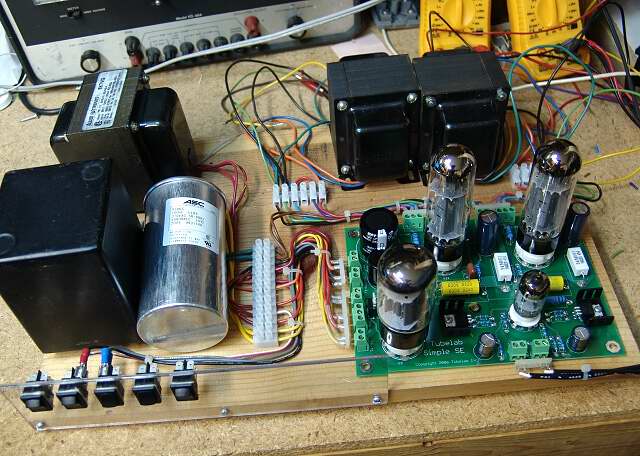
I plan to build and test a lot of these boards (5 so far) so I made this semi permanent bench test set up. The white terminal strips and the pins on the end of the wires (at the PC board terminals) allow the board or the transformers to be swapped out in a matter of seconds. You don't need to go to these extremes, but you should make all high voltage as inaccessible as possible. The primary wiring on the power transformer must be fused and isolated from contact. The metal frames for all 3 transformers and the PC board ground must be connected to the 3rd contact on the power cord. I tack soldered the transformer primary wires to a fused power receptacle, and ran 4 separate ground wires from the ground lug on the receptacle to the respective ground points. The power connector is housed inside a piece of PVC pipe to make it impossible to contact the line voltage. I use a switched surge suppressor for turning the amp on and off. I will also unplug the power cord and remove it from the workbench before working on the amp. This makes accidental turn on more unlikely.