The Simple P-P:
NOTE, This board is NOT available yet. It should be available in Q2 2009.
There are two P-P designs currently under development. The "Small" one, now called the Simple P-P, and the "Big" one, now called the Universal P-P driver. The Small one has progressed to the "third prototype PC board" stage. It is currently going through my rigorous testing, and I have been using it for several experiments. I plan to take this design through to a production PC board, but it will not be ready until the 2nd quarter of 2009.
The circuitry is not all that unusual. I Have already been informed that it bears a resemblance to SY's "red light district" amplifier, and Morgan Jones "Bevois Valley" amp. The truth is that it is about as simple of a P-P amp that I could come up with that yielded good performance. All three of these amps look like descendants of the Williamson to me.
Why have I done "yet another version of this common design?" I have breadboarded countless variations of small P-P amps. Some used the 6AQ5 tube, and some used the 6BQ5 / EL84 tube. Every amp was evaluated for performance, simplicity, and most important, the ability to be assembled by builders of varying skill levels and work the first time. One of the main requirements was for a stable design that didn't require any component tweaking to make it work. This design worked out to be the best. I chose the 6BQ5 / EL84 tube mostly because that is what was requested in the email that I received. The 6AQ5 is cheaper but produces slightly less power, and a slightly different sound. I may produce a 6AQ5 version of this board if there are enough requests for it.
As usual the board can be wired for triode, UL and pentode mode. Provision for global negative feedback is available. It can be used if needed, and it is needed in pentode mode.
There have been the usual delays due to "trying to keep my day job" activities and Sherri being away for much of the year, but the most recent delays are for two good reasons. I got some $1 output tubes that may work in this amplifier, so I had to try them out. It turns out that a PC board change was required. During the development of the original board I built a hybrid amplifier that used a tube - mosfet "Darlington" connection for the output. Again a PC board change was needed. The changes have been implemented and a prototype board made. The board works as expected with 6BQ5's but I have not tested the other combinations yet.
I have included some photos below.
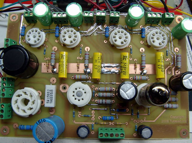
The first board, it hasn't seen any electricity yet.
A careful look will reveal my first problem with this board. The driver tube on the right is installed. The driver tube on the left, won't fit in the socket! The holes for pins 2 and 3 are smaller than the pins on the tube. Next time I'll look more carefully at the sockets before installing them.
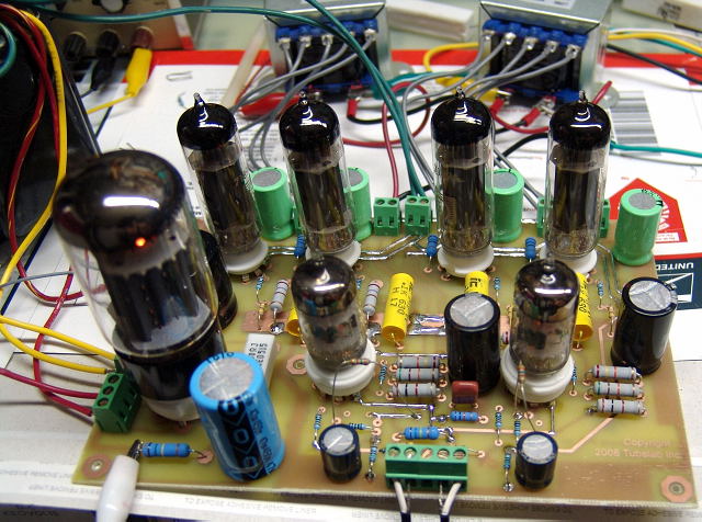
It is cranking some tunes here. The flying resistors are the GNFB resistors. I have not yet decided on an optimum value.
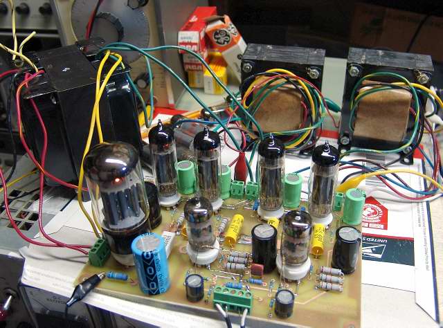
I added some much bigger transformers for much bigger sound.
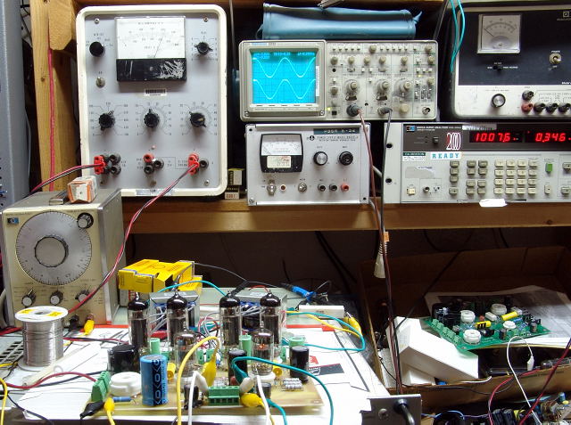
Board on test. Note the distortion number of 0.346%
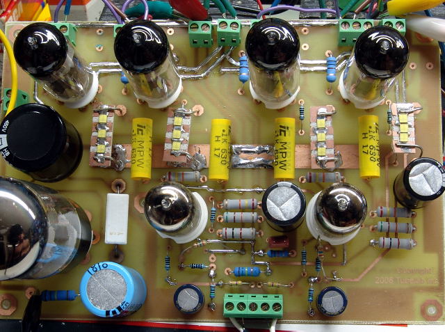
SY convinced me to try this. The cathode resistors and bypass capacitors have been removed and replaced with LED's. In this case three special LED's were mounted in series on a heat sink material. The amp does indeed sound fantastic with LED's in the cathodes of the output tubes. I am looking for an off the shelf LED that will work here. It may be included in the design.
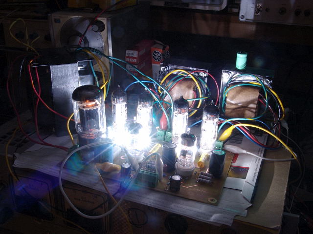
It can light up the whole room too!