![]()
![]()
![]()
![]()
![]()
Proper and Safe Use of a Multimeter
I have received considerable email of the subject of meters, ranging from what kind of meter to buy, to how to use it. Therefore I have created this page to share my thoughts. I have developed a method for setting up and testing a new amp that is centered around electrical safety, and reducing the possibility of electrical accidents. The basic premise is to have only one hand near a live electrical circuit at any given time. The procedure and photographs outlined below are based on the Tubelab SE amplifier, however the techniques can be applied to most electronic equipment. Please read and understand the electrical safety page before attempting to use a multimeter for the first time. Even though there is information specific to the Tubelab SE presented below, please read the entire page before attempting to probe a live circuit for the first time. Using a ground clip and ONE probe in ONE hand is MUCH safer than poking around in a live circuit with a probe in each hand.
What kind of meter do I buy?
I believe that most of the digital meters that are sold today are far more accurate than necessary for working on vacuum tube circuits. There are still some "experts" out there who believe that you should use an analog voltmeter for working on vacuum tube circuits. The best analog meters are not nearly as accurate as a $5 cheapie digital meter, so I don't follow that superstition. There is actually one case where an old analog meter is useful, due to its inherent low pass response. This is where you are trying to measure the DC voltage in the presence of a strong AC signal. This is where a scope comes in handy.
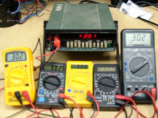
In order to test my theory that most cheap meters are good enough, I obtained several. I got some of the Cen -Tech units sold through Harbor Freight for less than $7 each (2 different types). I got one of each of the cheap meters sold by Jameco for about $10 each. I also got two of the Mastech MAS830L units from Jameco for $14 each. These are my favorites of the cheap meters for reasons that will be explained later. One sample of each meter was connected in parallel with the other cheap meters, my good ($100) Metex meter, and an old Fluke 8000 digital meter that had been professionally calibrated. At the voltage levels found in vacuum tube amplifiers, ALL OF THE METERS READ ESSENTIALLY THE SAME! I then tried different units of each type of meter and found that they were all plenty accurate.
So which meter do I buy? They all seem to be made in the same Chinese factory, using the same technology. They all seem to work about the same. The accuracy is about the same, although the accuracy specs vary from 1/4% to 1%, they all use 1% resistors inside. This leaves features and price as the decision points.
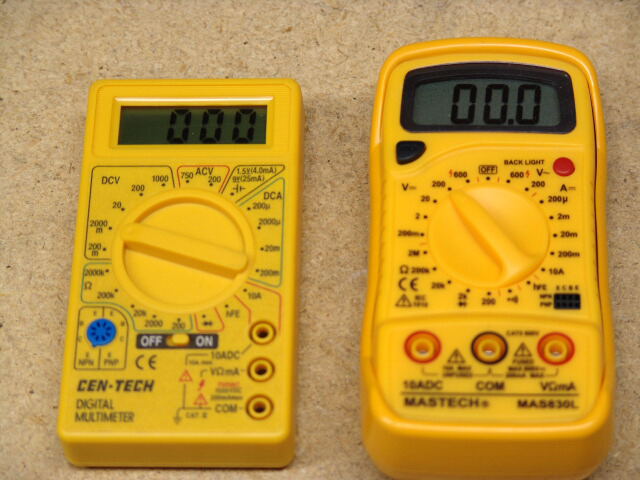
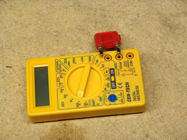
My favorite is the Mastech MAS830L from Jameco, $14. It is the larger unit on the right. For the ultimate in cheapness, try the Cen-Tech 90899-3BTB from Harbor Freight. This one shows up on their web site for $4.99, but is is listed in their sale flyer, and sold in the store for $3.99. It is the meter on the left. I am currently using both meters.
It is likely that sooner or later you will fry a meter, so make it a cheap one. Since these things have become ridiculously cheap, so there is no reason not to own a few. Actually, having a few will make your job much easier and safer when it is time to fire up your first amplifier. I must make one recommendation, get a meter with detachable (replaceable) leads. You will want to replace them at the first sign of wear, and you want to be able to plug in different types of leads. If you want to set up a first class lab, get one good meter and several cheap ones. Only use the good one when its performance is needed (not often).
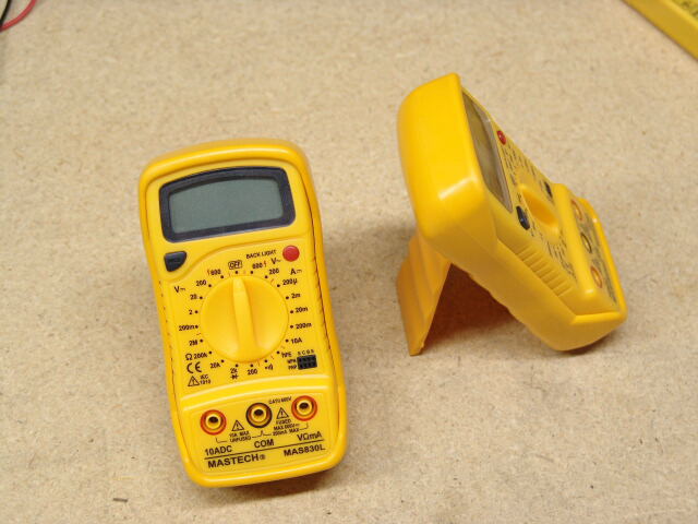
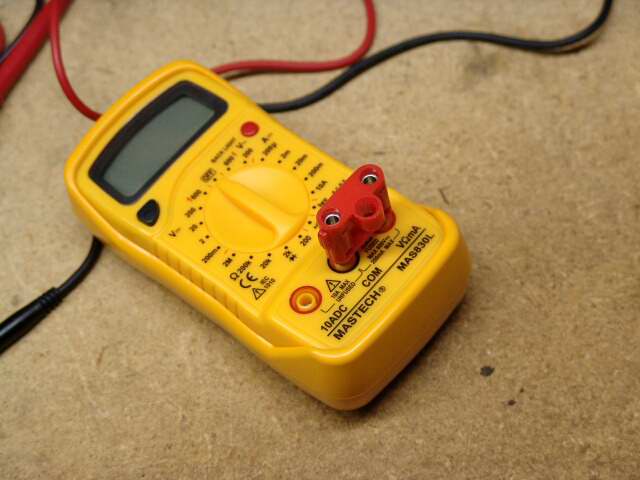
Why do I like the MAS830L? There are several small reasons. First, it has a slightly larger display than the others. It has a backlit display, although it will kill the battery quickly, so only use the light when you need it. It has a fold out stand which allows the unit to stand up without aid. This feature is needed when you want to read the meter from a safe distance away. The input jacks are spaced such that standard dual banana plugs can be inserted. This is great when you want to make your own leads, or use custom connections. The dual banana plug will not fit any of the other cheap meters. All of these meters come with a basic set of probes. The probes that come with the MAS830L are a little sturdier than some of the others. The input jacks are deeper that those on the other meters. The Mini - Grabber probes (also from Jameco) fit without bottoming out. These leads bottom out on all of the other meters leaving some exposed metal, this is a possible shock hazard.
Basic Meter Use:
The term multimeter applies to the devices shown on this page. The term comes from the fact that they are meters with multiple uses. There are fancy multimeters with many features like temperature measurement, frequency measurement, signal generation, transistor testing and more. We are concerned with 4 basic measurements DC voltage, AC voltage, current, and resistance. It is very important to realize that connecting the meter up improperly or setting the knob to the incorrect setting can (and usually will) permanently damage the meter and can cause damage to the circuit to which it is connected. Decide which of the 4 basic measurements is being made, and set the meter to the highest appropriate range BEFORE going near a live circuit. This is very important on meters that have the power switch incorporated into the main dial.
The digital chip inside these meters is a voltage measuring device. The chip can (usually) measure from zero to 200 millivolts DC, with great accuracy. All of the other functions AC voltage, resistance and current are handled by converting the input signal into a 0 to 200 millivolt DC signal. This means that if you are using the 200 millivolt DC range, you are connected directly to the digital chip with no resistors in the path. This range is the most susceptible to damage if seriously overloaded. Only use the 200 millivolt DC voltage range if you are sure that the input voltage is less than 200 millivolts. On other DC voltage ranges an internal voltage divider (resistors) scales the input to 200 millivolts max. It is the accuracy of these resistors that determines the meter's accuracy. When measuring current the meter actually measures the voltage drop across an internal resistor and computes the current. When measuring resistance the meter forces a known current through the unknown resistance and measures the voltage drop. When measuring AC voltage the meter rectifies the AC into DC and divides it down to 200 millivolts max. Since the rectification process is nonlinear at low voltages, cheap meters do not have low voltage AC ranges. To accurately measure a 6.3 volt filament voltage, I will use my good meter. Cheap meters don't do AC current either.
First note that most meters have three input jacks (some have four) one is marked COM, the black lead goes there. Another jack is marked V(ohm)mA, the red lead goes there for most measurements. The third jack is a high current jack usually marked 10ADC (sometimes it is 20 or some other number). This jack is used only for high current measurements. The four jack models use separate jacks for current measurements, this makes accidentally setting the meter to a current mode harder, but it still can be set to resistance. For vacuum tube electronics we can usually ignore the high current mode. Put your test leads into the COM and V(ohm)mA jacks and leave them there.
Making a Voltage Measurement:
Before attempting to make a voltage measurement, think about the anticipated result. Is this a DC or AC voltage? How much voltage will be present? If things are not working correctly what is the highest voltage that I might find? A voltage is ALWAYS measured between TWO points. Is one of those points GROUND? If not, can you make a different measurement such that one of the measurement points IS GROUND? If your measurements are all referenced to GROUND (the usual case), you can connect the black lead to GROUND with a clip (see below), and probe the other point with the red lead.
Set the selector switch on the meter to the range that is higher than the maximum anticipated voltage of the appropriate type (DC or AC). If the maximum anticipated voltage is not known, set the meter to the highest range available. Wherever possible connect the meter into the circuit when the circuit is OFF, then power up the circuit without touching anything. Read the meter, then turn the circuit OFF. If the reading is lower than the next available lower range on the meter you may set the meter to a lower range while the circuit is on. When doing this touch ONLY the meter with ONE hand, and be careful to only lower the meter one range, allow the readings to stabilize (2 or 3 seconds) before proceeding lower. Accidentally setting the meter to a current of resistance range can damage the meter, and the circuit it is connected to. If the circuit has sufficient power the meter can explode or burst into flames. I know from experience that this will happen if you try to measure the resistance of the wall outlet. Most modern meters are "fuse and diode protected" this is to prevent fireworks, but will not usually save the meter from an overload of this magnitude.
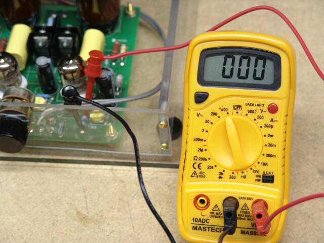
Below, the meter is connected into the circuit before it is powered up, and set to the 600 volt DC range, since I am assuming that I don't know how much voltage is present.
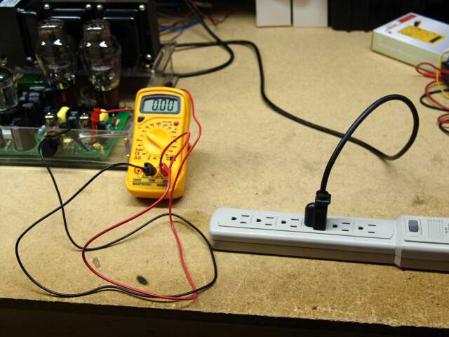
Next, the circuit is powered up. I always use an extra power strip for the circuit under test. I put it in a very convenient place, where it is easily accessible.

Since the meter reads 3 volts, I can safely lower the range. Below, the meter is set to the 200 volts DC range.
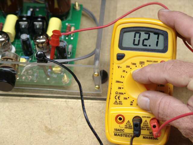
Since the meter reads 2.7 volts, I can again lower the range to the 20 volt DC range.

Since the meter reads higher than the next lowest range, I am done.
An AC voltage measurement is made in the same manner, except using the AC voltage ranges. It is very important to use ONLY voltage ranges when ANY voltage source is connected to the meter. Accidentally selecting a resistance or current range will cause fried meters, parts, and nerves, followed by a generally unhappy feeling.
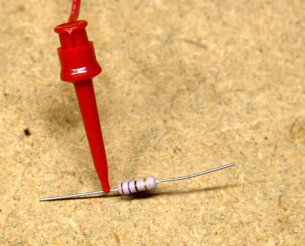
Making a Resistance Measurement:
Resistance measurements are the easiest to make. It is important to remember that resistance measurements can ONLY be made on a dead (no voltage) circuit. The multimeter sends a tiny current into the unknown resistance and measures the resulting voltage drop. If there is any voltage present it will upset the readings. Even the residual charge left in a capacitor can cause incorrect readings. If you are going to measure the resistance in a complete circuit discharge any capacitors present before making any measurements.
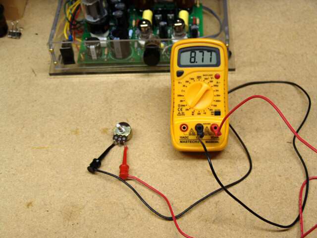
Making the measurement is simple. Connect the unknown resistance to the meter leads and turn the meter to all of the resistance ranges. Select the reading that provides the best accuracy. Measuring semiconductor devices is tricky since the resistance actually changes depending upon how much current is flowing through them. Most meters have a range or mode especially for this purpose. Consult the manual for your particular meter. In the photo below the meter is on the 20K ohm range so this part is 8.77K ohms.
Making a Current Measurement:
The current measurement is the most difficult of the basic measurements, and has a high potential for fried meters. A true current measurement is usually not needed since many times measuring the voltage across a known resistance can be used to determine the current. Setting the bias current in a tube amplifier is very important to us. Most amplifiers have a resistor in the cathode circuit, so you simply measure the voltage across this resistor, and calculate the current. Sometimes the circuit design does not allow for a cathode resistor. In this case a resistor is often provided in the plate circuit. This is the case in the Tubelab SE. Measuring the voltage requires a voltage measurement that is not GROUND referenced. This measurement is explained later.
In order to make a true current measurement the current must flow THROUGH the meter. This means that the circuit must be broken and the meter inserted in SERIES with the circuit. Some amplifiers have "bias monitor jacks" for this purpose. There are "bias buddy" type devices that plug in to the tube socket, and the tube plugs into it, also for this purpose.
Since the current flows through resistors, called shunts, INSIDE the meter and through the meter's switching circuits, most meters have an upper limit of 200 milliamps for the standard jacks. There is a separate high current jack that is wired through a high current shunt directly to the COM terminal. This means that most meters (including the expensive ones) do not have any current ranges between 200 milliamps and 10 amps.
We will proceed through a simple example below. We have a tube connected to a power supply which provides 12.6 volts for the filament. The tube manual tells us that it should draw 150 milliamps. We want to measure this current.
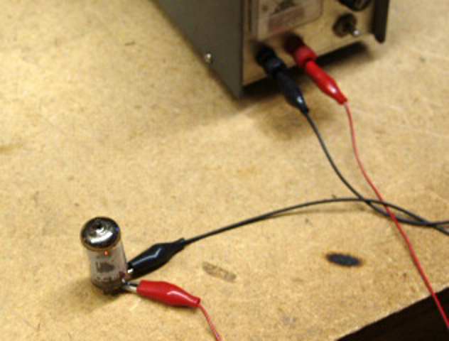
We must break the circuit and insert the current meter in series. Again start on the highest range and work down. This time the highest standard current range (200mA) is the correct one.
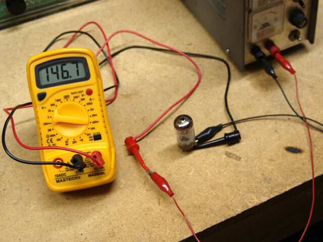
The meter reads 146.7mA, this is quite close to the published value. If the circuit was not so simple, finding the proper place to break it would not be simple either.
Probes:
The probes that come with these meters are useful for most basic measurements, but they are not the best solution to making measurements on a high voltage system. I prefer some type of clip - on device that can be attached to the circuit before power is applied. These are connected, and the meter is set up before power is applied. This way all measurements can be made without coming near the live circuit. Since these meters are cheap, several can be connected to the circuit at a time. If a meter is connected to each power supply point, and several critical points, the health of a new circuit can be determined instantly as soon as the power switch is turned on, just by looking at the meters. That way the power can be turned off quickly if there is a problem.
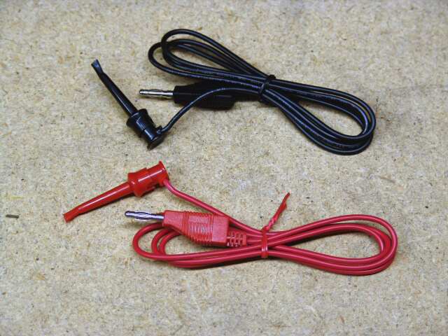
There are two types of clips that fit this requirement. Alligator clips and Mini - Grabbers. Meter leads with each type of clips on the end are available, although many of the alligator type clips are too large to be used on a PC board. The Mini - Grabber clips are excellent for this type of use, but they can not be used to grab a large (#12) wire. Below is a picture of the Mini - Grabber leads from Jameco. Part number 21856 is black, and number 21864 is red. These are $4 each and the quality is OK but not great. I did not search for better ones.
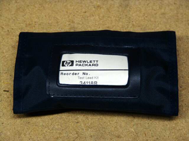
It is also possible to get a lead set with interchangeable ends. I got this one at a hamfest several years ago, but I see them on Ebay every once in a while. These were ridiculously expensive new, but can be found surplus for about $10 to $20. They were also used by the Army, so they can be found in military surplus packaging. These are very high quality units.

It is possible to make your own lead set. It is not recommended that you do this unless you are sure that you can make better ones than the Chinese ones from Jameco. Remember that your LIFE may depend on your test leads. NEVER try to splice, or repair damaged leads. Don't try to tape any bad spots, toss them. The wires MUST be in good shape, with absolutely no bad spots in the insulation. The leads carry the FULL VOLTAGE that you are measuring. The only reason that I have made my own leads is to make them shorter that normal to reduce bench clutter in multiple meter situations. I must admit that I have made my own leads with Teflon covered wire. Why? Because it is tough, it doesn't get damaged easily , and it won't melt if it meets the soldering iron or hot tubes. I have built a specialized meter that reads up to 5000 volts, for use on high power SE tube amps. I have also built amps that need it. You can't buy leads for this at WALL - MART, you must make your own.
Clips or Probes?
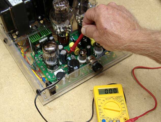
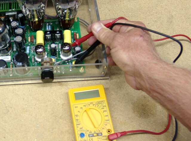
Why do we want clips? Well lets suppose that we want to measure the voltage on a circuit in a vacuum tube amplifier. With conventional probes, we would turn the amp on, then with one probe in each hand, touch them to the circuit to be measured. This puts both hands in the vicinity of high voltage. This is potentially unsafe, yet this is the way many of us have learned to make measurements. I don't recommend doing this. You will notice that the amp is actually OFF in the picture.
If you are making a measurement that is referenced to GROUND, then use a black lead that has a clip attached, with the clip connected to circuit GROUND. Now I am probing with ONE probe in ONE hand. This is a MUCH safer situation, and I generally make probed measurements this way.
Sometimes the measurement is NOT referenced to ground. Now what? Well, if you are the kind of person who can eat with chopsticks, then maybe you can handle two probes in one hand. This is safer than one probe in each hand. I really don't recommend this either, but if you do it, don't touch ANYTHING with your other hand.
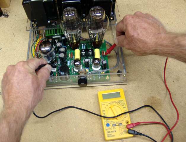
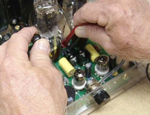
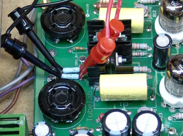
Now what happens when we need to make an adjustment while probing the circuit. Here, I am probing the bias points with my right hand, and setting the current with my left hand. Since I am watching the meter, I am not watching what I am doing! The bias points are between the two output tubes on this amp, and these tubes get rather hot, so this is a recipe for bad language, or worse. There must be a better way!
The Multiple Meter Approach
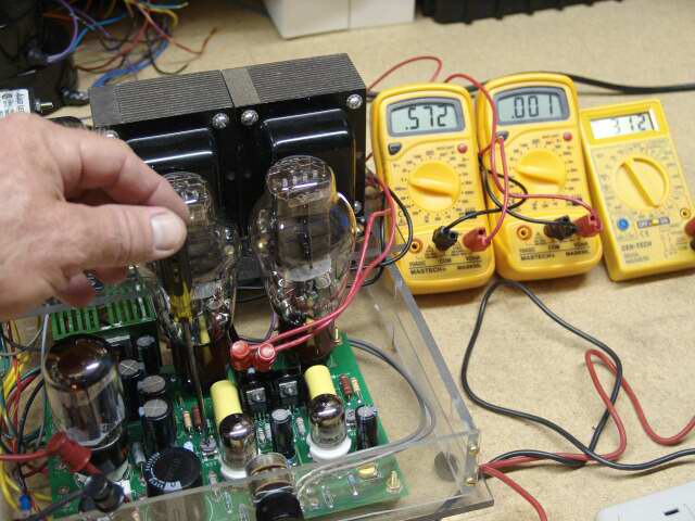
Since these multimeters cost less than some of the parts used in this amplifier, it makes sense to use more than one. Hook them all up to the amplifier BEFORE turning on the power, and then simply stand a safe distance away, and flip the switch. No fingers (or any other body part) near the electricity. When you have to make adjustments, then one hand, on an insulated screwdriver goes near the amplifier. The other hand (and the rest of your body) does not touch ANYTHING. This procedure makes electric shock very unlikely. Below you will see three meters connected into a Tubelab SE amplifier. The large meters indicate the bias current for each channel and the small meter indicates the B+ supply voltage. It is always a good idea to have a meter on the B+ supply when powering up a new circuit. It gives a quick indication of circuit health, and an indication of how much stored charge is left after the amp is turned off. Here the bias is adjusted with one hand, and little chance of being shocked or burned. It is easy to tell that the left channel is set to 57.2 mA, the right channel is still zero (not set yet) and the B+ is 312 volts. For this amplifier design, I would consider 3 meters the minimum for initial setup. Full details on initial testing of the Tubelab SE amplifier are furnished on the CD that is included with the board. This can be accomplished with 3 meters. They can all be the $4 type if you desire.
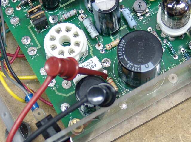
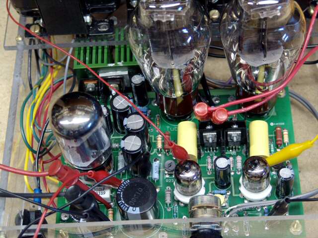
Going to the other extreme, I am going to wire an amplifier up for some comprehensive tests. I want a meter on all of the important points. Below we attach a pair of clips to the right channel bias shunt (R18). The tubes have been removed so that they don't get in the way.
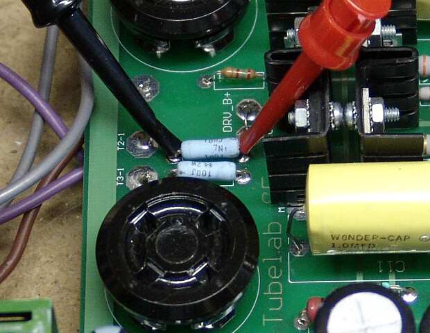
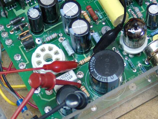
Here the clips are applied to the left channel bias shunt (R29).
Here clips are applied across R30 which is the main B+ bleeder resistor
Here the clips are attached to the B- (bias) bleeder (R7). I ran out of Mini - Grabbers, so I used small alligator clips.
Now two more sets of clips have been attached. these monitor the drivers plate voltage, which must be adjusted. The left channel meter connects from C11 to GROUND. The right channel meter connects from C9 to GROUND.
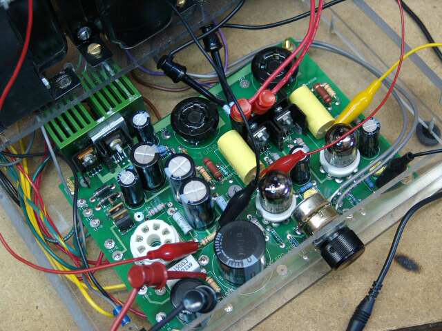
Now the tubes can be installed and the amp connected up
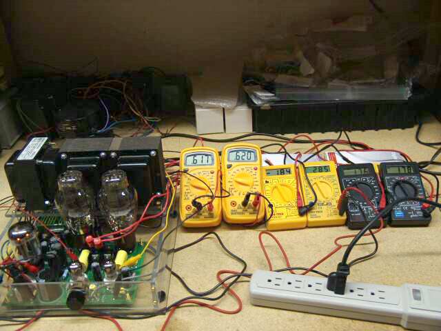
Next, each set of leads gets its own meter.The power strip is the master power control here since it is easier to get at than the amplifier's power switch. All of the excess wire from the meter leads is gathered up behind the amp and the meters. The cheap meters are propped up with boxes so they can be easily read. Anything that is not needed is removed from the immediate area.

Now it is time to flip the switch, since this is a working amplifier, nothing bad is going to happen. The meters show left channel 300B bias is 61.7mA, right channel 62mA. Main bias voltage -184, main B+ voltage 285 volts. The left 5842 plate was set to 176 volts. The right 5842 plate is 178 volts.
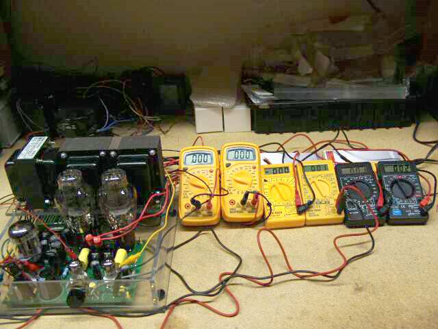
Here the power strip has been turned OFF and the meters all read near zero. After all meters are reading less than 5 volts, it is safe to approach the amplifier.
After the voltage had decayed to very low values, the power strip, and the power cord were removed from the work bench. This makes accidental turn - on impossible.
I will leave the power strip and the power cord on the other bench while doing any work on the amplifier. This means that two actions are required to power up the amplifier. This makes accidentally powering up the amplifier while working on it unlikely.